
7114 Harry Hines Blvd.
Dallas, Texas 75235
214-357-3851
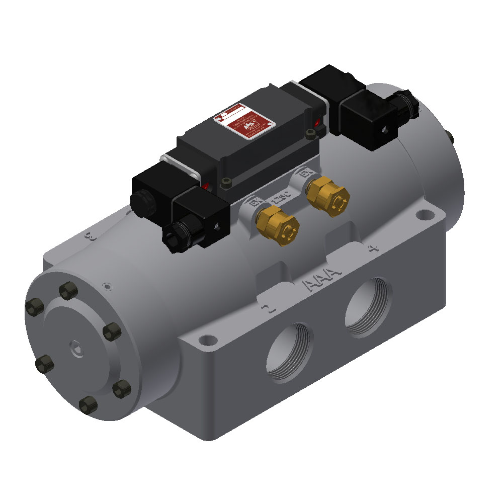
Data for ESS12AC
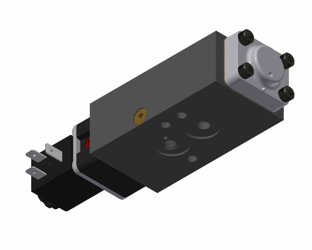
Details for ESS12AC
Vacuum: The valve cannot be vacuum operated when the solenoid is internally piloted.
Temperature: -20°F to 120°F ambient. Caution: If it is possible that the ambient temperature may fall below freezing, the medium must be moisture free to prevent internal damage or unpredictable behavior.
Mounting: The spool is friction positioned so the valve must be mounted with the spool in a horizontal orientation.
O-Rings: Buna-N in main valve, Viton in control valve.
Solenoid Seat: Viton.
Materials: 356-T6 aluminum body aluminum body, hard anodized aluminum spool, A380 aluminum end caps, Viton solenoid seat, composite gaskets, steel fasteners.
Flow: 1627 SCFM, 37.8 Cv
Repair Kits: ERKV-16 & ERKV-3.
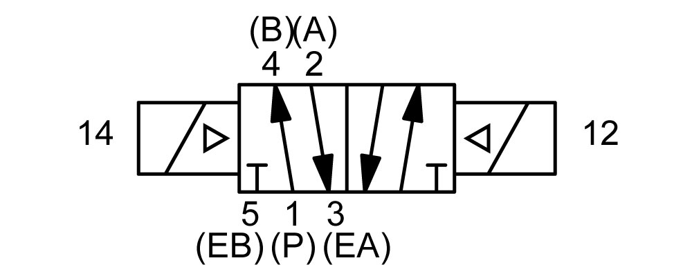
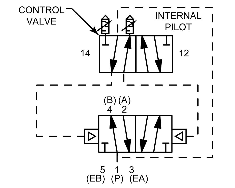
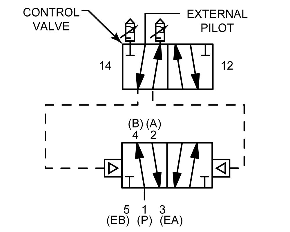
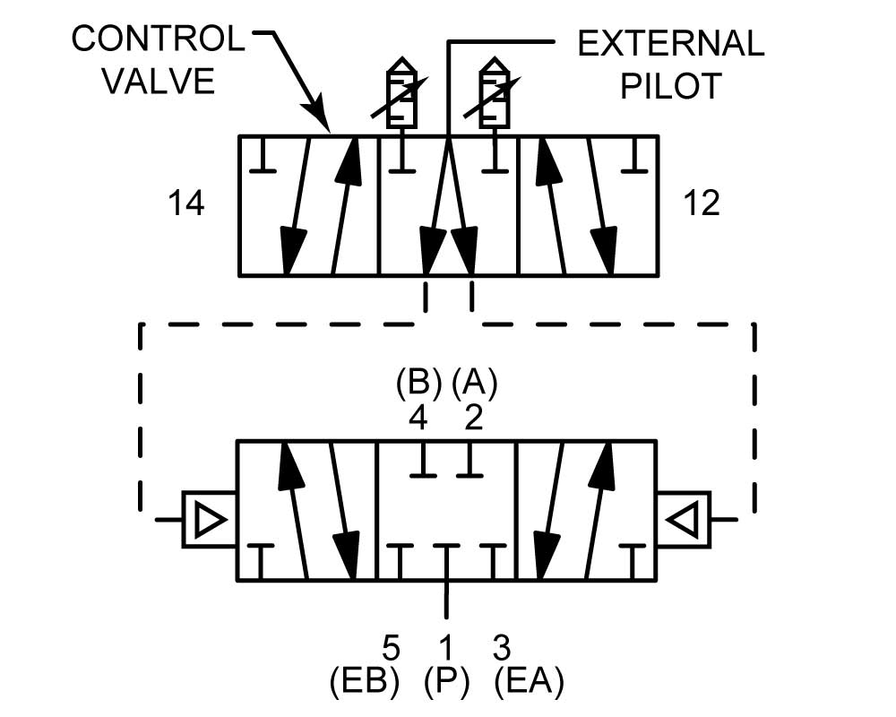
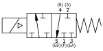
3-Way or 5-Way: This valve is basically 4-way, it must be configured for external pilot (Option 'Z') for 5-way service by using ports 2 or 4 as an inlet, or 3-way service by plugging the unused port 2 or 4.
Fluid Media: Soft seal models are made for air, vacuum, and gases compatible with component materials. They should not be used with liquids.
Weight: 27.7 lbs ± 5%.
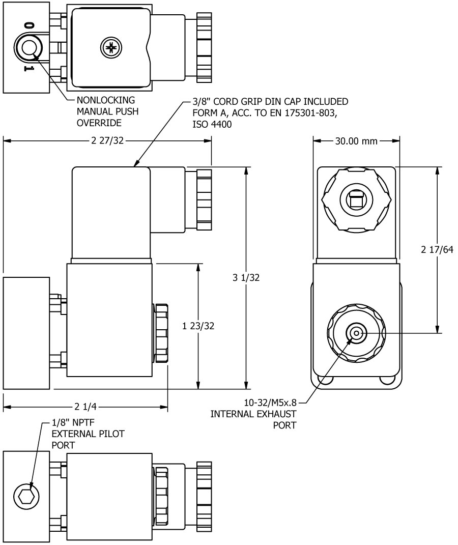
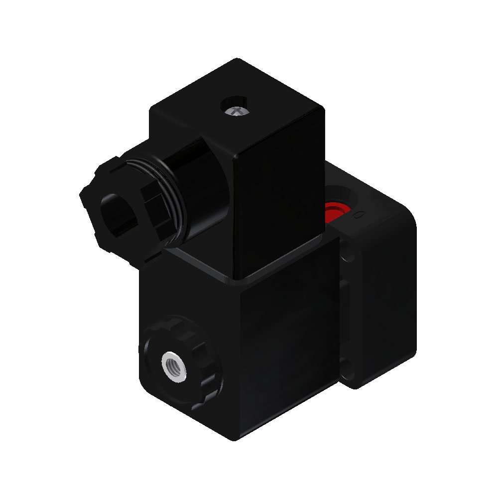
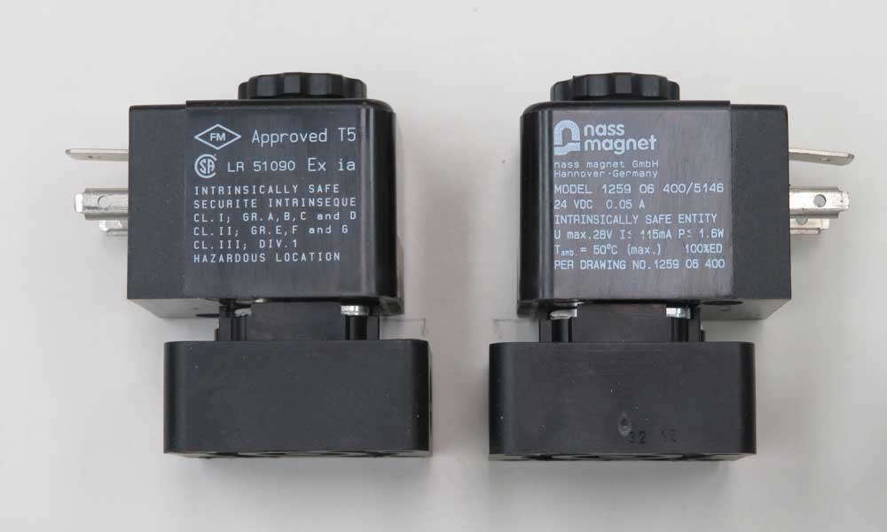
"E-Series" Coil - Option A - Intrinsically Safe
These operators are equipped with the standard V-562 nut but can be ordered with a V-567W bronze muffler nut (option L) or a V-562 side exhaust nut (option C).
These 24 VDC coils are approved according to EN 50 020 respectively DIN VDE 0170/0171 part 5 for hazardous location. Class I, groups A, B, C and D; Class II, groups E, F and G; Class III. This coil is an ISO 4400 DIN style pin pattern. A non-indicator, cord grip style cap is provided. A copy of the certification is available here. An approved cap (included) must be used when connecting to an electrical source. The longer tab is the ground (earth). Either shorter tab can be connected to hot (+) and the other connected to neutral (-).
Molding Material: Thermoset resin.
Ambient Temperature: -20°C to +50°C.
Internal Diameter Orifice: 0.8mm
Relative Duty Cycle: 100%.
Degree of Protection: IP65 with connector.
Certifications: This coil carries the following certificate of compliance. The rating only applies to the coil/operator and not the entire valve.
Insulation Class: F
Electrical Characteristics: 21.6 - 28 VDC
"E-Series" Intrinsically Safe Barrier
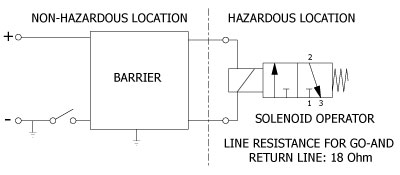
COMPATIBLE BARRIER MANUFACTURERS
Pepperl & Fuchs Inc. - Telephone (330) 425-3555 - FAX: (330) 425-4607
Pepperl+Fuchs, Inc., 1600 Enterprise Parkway, Twinsburg, Ohio 44087
E-mail: sales@us.pepperl-fuchs.com - www.pepperl-fuchs.com
Models: KFD2-SLS-EX2 and KFD2-SD-EX1.36
Eaton
Process Safety Automation Measurement
www.eaton.com/us/en-us/products/process-safety-automation-measurement/intrinsic-safety
Model: MTL5525
STAHL, INC - Telephone: (800) 782-4357
R. Stahl, Inc.
13259 N. Promenade Blvd, Stafford, TX 77477
E-Mail: sales.us@r-stahl.com - www.rstahl.com
Model: 9275/10-24-48-11s
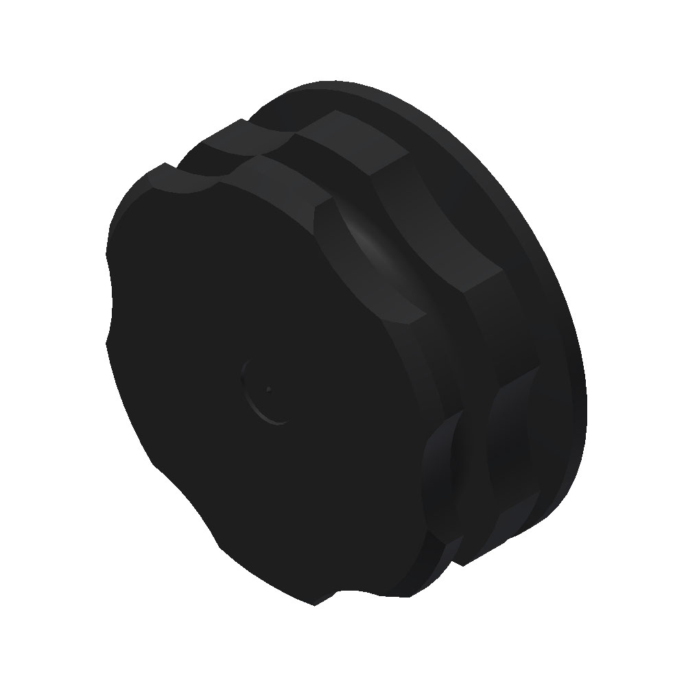
"E-Series" Nut - Side Exhaust
General - 1-1/2" & 2" Valve Operation
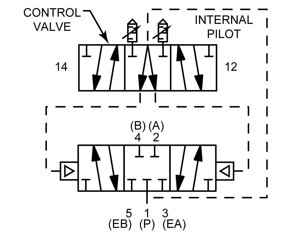
Normal assembly of all standard 1-1/2" & 2" valves is for internal pilot operation, in which the air pressure for shifting the large spool is internally tapped off the valve inlet. If the main spool is to handle pressures lower than 50 PSI or more than 150 PSI on
Normal assembly of all standard 1-1/2" & 2" valves is for internal pilot operation, in which the air pressure for shifting the large spool is internally tapped off the valve inlet. If the main spool is to handle pressures lower than 50 PSI or more than 150 PSI on solenoid models or from 50 to 250 psi on all other models, the valve should be factory ordered for "external pilot operation" by adding suffix "Z" after the regular model number. Or, the valve can easily be converted in the field to external piloting as described below. This pressure limitation applies to all 1-1/2" and 2" manual lever, solenoid, pilot or differential pilot valves.
Conversion to External Piloting: Remove the entire control valve from the main body and lay it aside. Install a 1/16"-27 NPT pipe plug in the treaded hole uncovered in the body mounting pad. Re-mount the control valve in the same orientation as before. Connect a pilot pressure air source (50 to 150 PSI on solenoid models and 50 to 250 psi on all other models) to the 1/4" NPTF external pilot port. This port is located on the side and near the top of the main body and stamped "EXT P", on the side opposite the MFC flow controls.
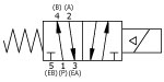
2 POSITION VALVES
2 POSITION VALVES
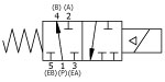
3 POSITION VALVES
3 POSITION VALVES
General - Installation & Maintenance
Bulletin A-113: Operating & Maintenance Instructions.
Installation: Valve Fitting Installation.
 WARNING:These products can expose you to chemicals which is(are) known to the State of California to cause cancer or reproductive harm. For more information, go to www.P65Warnings.ca.gov. Contact us for specific chemicals or materials used in a product.
General - Lubrication, Standard
The shelf life of Magnalube-G regularly lasts for 10+ year intervals in closed packaging due to the extremely long operating life of the Elastomer-PTFE gelling agent and premium parafiinic mineral base oil. If the valve is stored for over 2 years, then a small reapplication of grease is suggested.
Magnalube-G Technical Document
Magnalube-G MSDS Document
An alternative grease for low temperature application, refer to Dow-55 grease.
General - O-Ring Information
| Dash No. | O-ring Description | Temperature Rating |
|---|---|---|
| -2 | Silicone | -80°F to 400°F |
| -3 | Viton for most aromatic gases | -20°F to 400°F, 600°F for short time |
| -7 | Urethane, 70 Durometer | -65°F to 200°F |
| -9 | Buna-N | -40°F to 250°F |


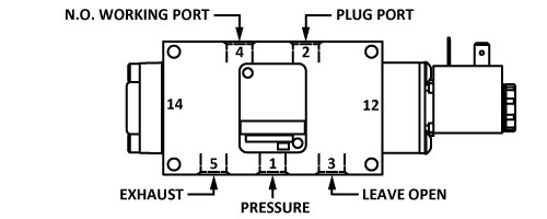 3-WAY N.O. APPLICATION
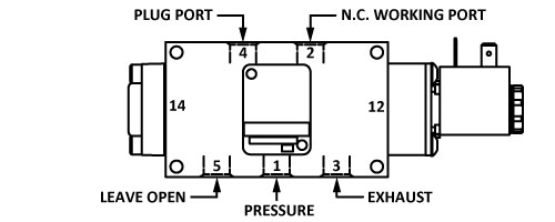 3-WAY N.C. APPLICATION


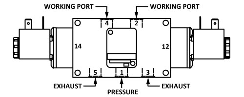 4-WAY APPLICATION
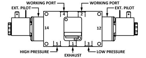
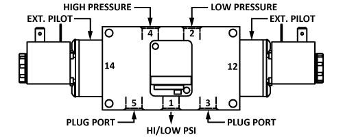 5-WAY APPLICATIONS