7114 Harry Hines Blvd.
Dallas, Texas 75235
214-357-3851
Valve Data Extra Information
"Classic" Operator & Coil - Standard
Materials: Steel, stainless steel, thermoset polyester molded resin coil, Buna-N seat & O-Ring.
Repair Kit: RKPSV-1 includes plunger, spring & O-Ring.
Ambient Temperature: -4°F to +120°F.
Relative Duty Cycle: 100% (continuous voltage).
Degree of Protection: NEMA 1.
Voltage Tolerance: ± 10%.
Resistance Tolerance: ± 8% at 20°C.
Orifice Size: 3/64" base, 1/16" stem.
Insulation Class: B
*Coils: The encapsulated coils are UL approved. The coil is marked or embossed with QC130, QC155, or QC180. UL Document.
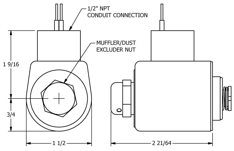
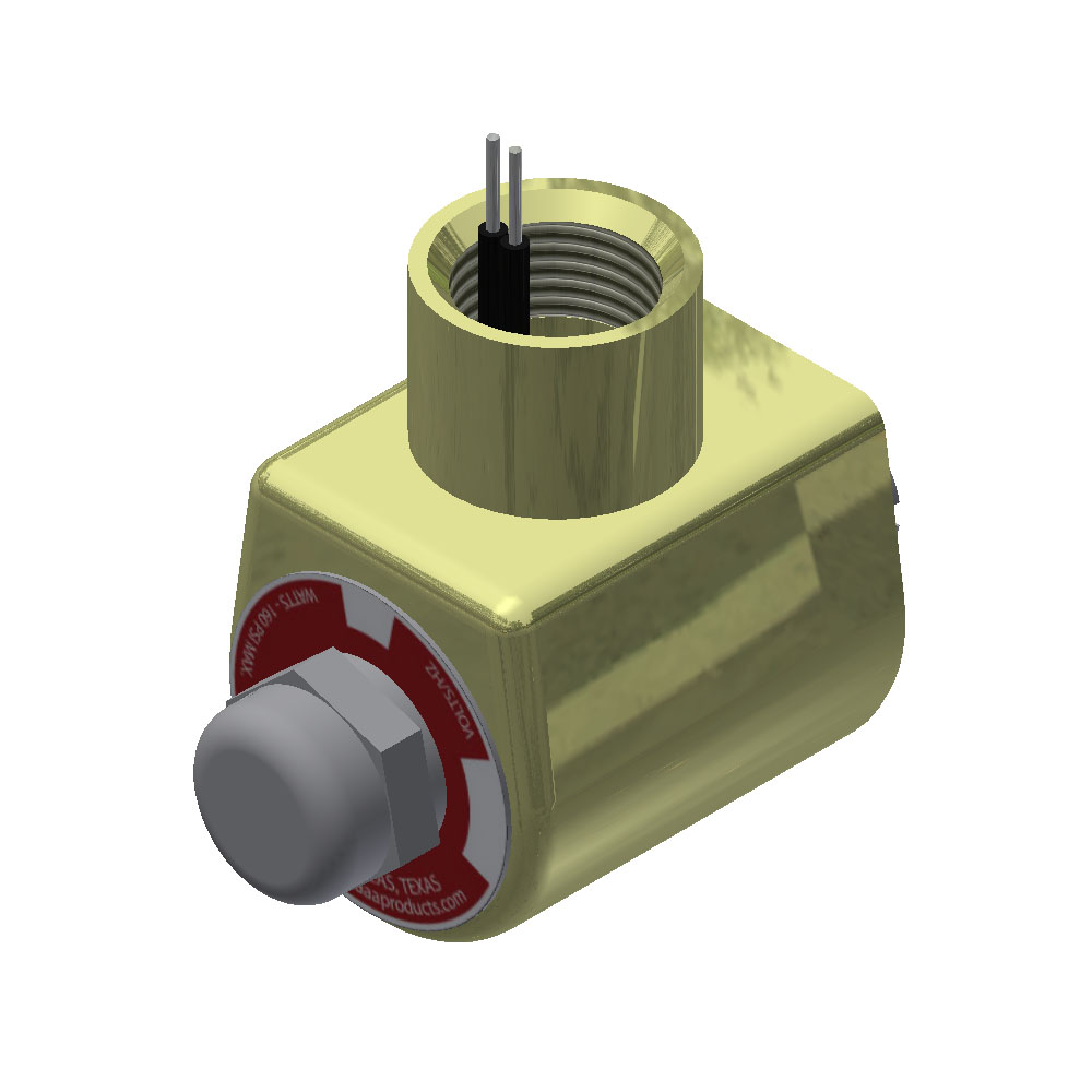
"Classic" Operator & Coil - Standard w/Dust Excluder Nut
Materials: Steel, stainless steel, thermoset polyester molded resin coil, Buna-N seat & O-Ring.
Repair Kit: RKPSV-1 includes plunger, spring & O-Ring.
Ambient Temperature: -4°F to +120°F.
Relative Duty Cycle: 100% (continuous voltage).
Degree of Protection: NEMA 1.
Voltage Tolerance: ± 10%.
Resistance Tolerance: ± 8% at 20°C.
Orifice Size: 3/64" base, 1/16" stem.
Insulation Class: B
*Coils: The encapsulated coils are UL approved. The coil is marked or embossed with QC130, QC155, or QC180. UL Document.
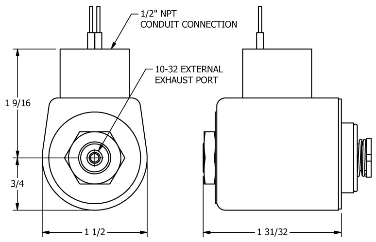
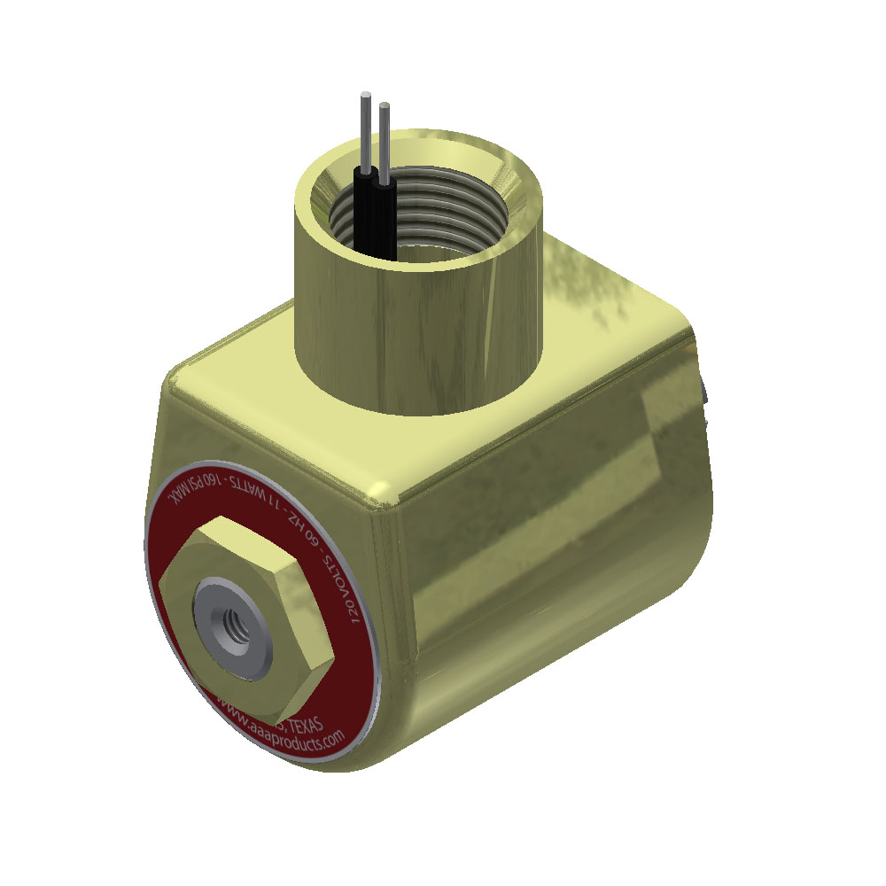
"Classic" Operator & Coil - Standard w/Tapped Exhaust
Materials: Steel, stainless steel, thermoset polyester molded resin coil, Buna-N seat & O-Ring.
Repair Kit: RKPSV-1 includes plunger, spring & O-Ring.
Ambient Temperature: -4°F to +120°F.
Relative Duty Cycle: 100% (continuous voltage).
Degree of Protection: NEMA 1.
Voltage Tolerance: ± 10%.
Resistance Tolerance: ± 8% at 20°C.
Orifice Size: 3/64" base, 1/16" stem.
Insulation Class: B
*Coils: The encapsulated coils are UL approved. The coil is marked or embossed with QC130, QC155, or QC180. UL Document.
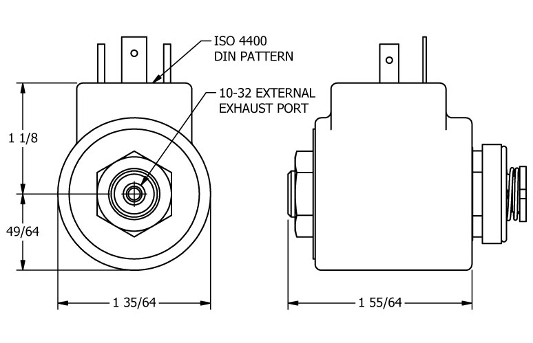
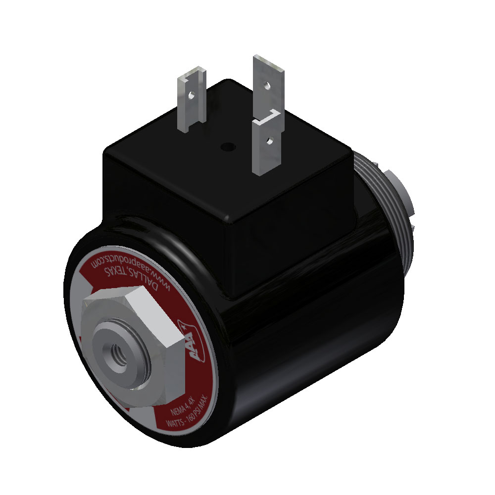
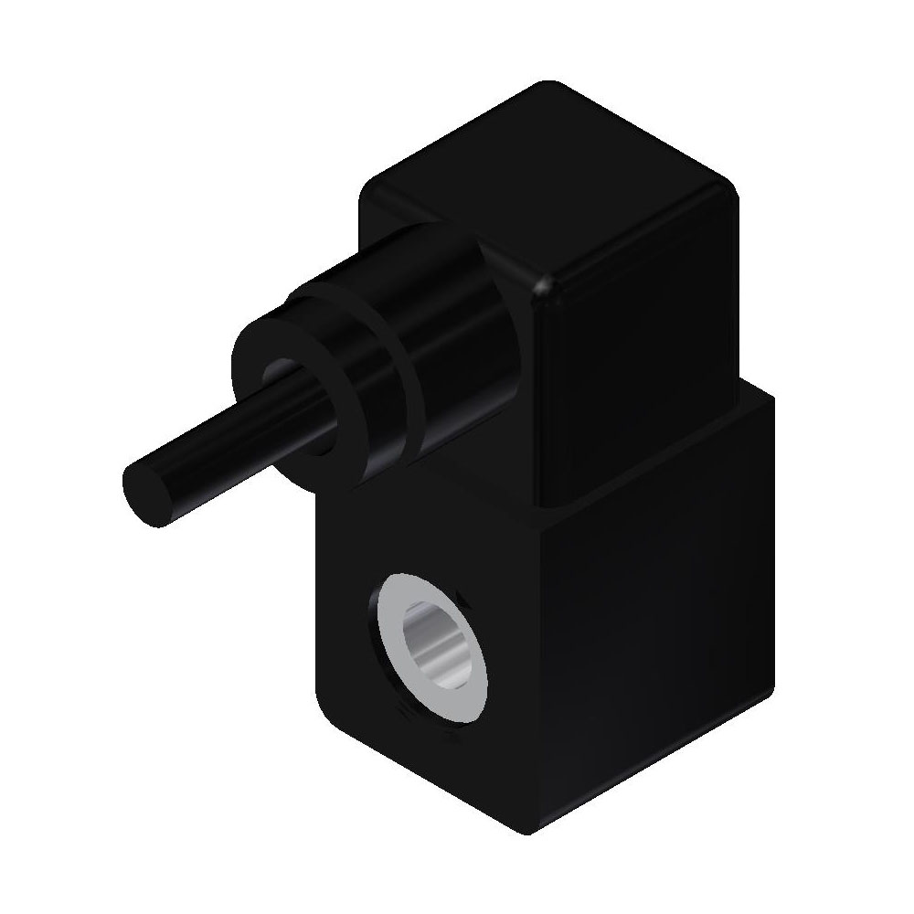
"Classic" Operator & Coil - DIN Style
Materials: Duroplast/thermoset resin, Buna-N seat & O-Ring.
Repair Kit: RKPSV-1 includes plunger, spring & O-Ring.
Ambient Temperature: -4°F to +120°F.
Relative Duty Cycle: 100% (continuous voltage).
Degree of Protection: NEMA 4 & 4X with connector.
Voltage Tolerance: ± 10%.
Resistance Tolerance: ± 8% at 20°C.
Orifice Size: 3/64" base, 1/16" stem.
*Coils: The encapsulated coils are UL approved. The coil is marked or embossed with QC130, QC155, or QC180. UL Document.
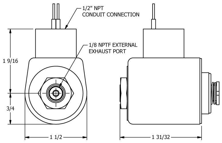
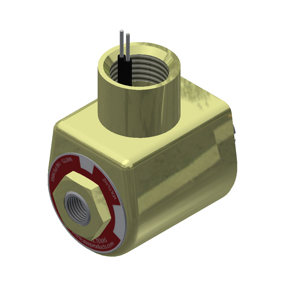
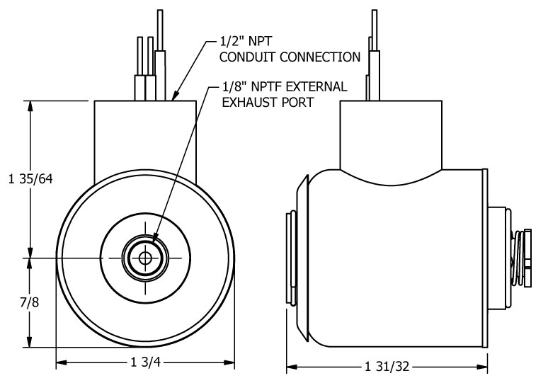
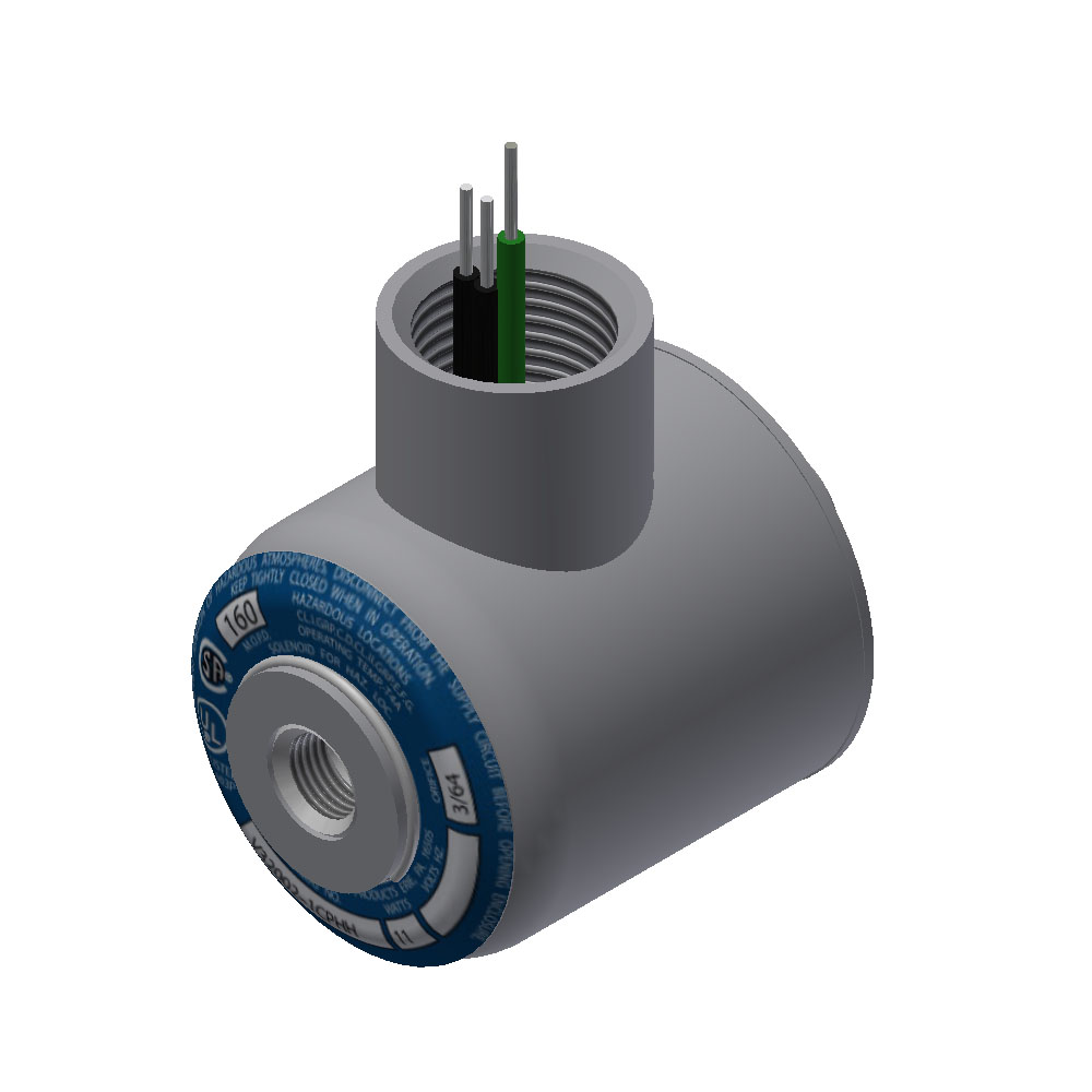
"Classic" Operator & Coil - Explosion Proof
Materials: Steel, stainless steel, thermoset polyester molded resin coil, Buna-N seat & O-Ring.
Ambient Temperature: -4°F to +120°F.
Relative Duty Cycle: 100% (continuous voltage).
Certifications: UL & CSA label for Class I, Division 1, Group C and D, Class II, Division 1, Groups E, F and G. CSA file number 087427_0_000. UL file number E37005
Voltage Tolerance: ± 10%.
Resistance Tolerance: ± 8% at 20°C.
Orifice Size: 3/64" base, 1/16" stem.
Insulation Class: B
Commonly Asked Questions
A: Yes. If equipment has been approved for use in a Division 1 hazardous location, it can be used in a Division 2 hazardous location, providing it is in the same class and group.
A: No. Equipment used in Class I and Class II hazardous locations are made for different purposes. Equipment approved for Class I hazardous locations must contain an internal explosion, while Class II approved equipment must seal out dust. They are not interchangeable.
A: No. The requirement for explosion proof certification requires a high potential test that must be completed on the operator/valve.
A: No. The requirements for explosion proof require extremely tight fitting components. Rotating a canister after installation could rotate the stem out of the adaptor and cause leak or operation issues. Contact the factory for how to specify coil rotation/orientation when ordering. The standard 1/2" conduit will be rotated towards the 2 port side of valve body.
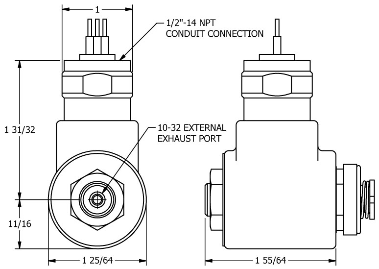
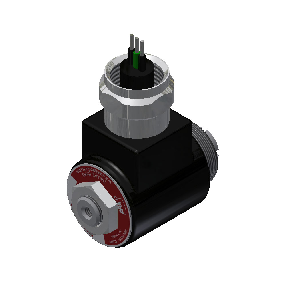
"Classic" Operator & Coil - Mold-Over
Materials: Zinc plated steel hub, molded coil, Buna-N seat & O-Ring.
Repair Kit: RKPSV-1 includes plunger, spring & O-Ring.
Ambient Temperature: -4°F to +120°F.
Relative Duty Cycle: 100% (continuous voltage).
Degree of Protection: NEMA 4 & 4X.
Voltage Tolerance: ± 10%.
Resistance Tolerance: ± 8% at 20°C.
Orifice Size: 3/64" base, 1/16" stem.
*Coils: The encapsulated coils are UL approved. The coil is marked or embossed with QC130, QC155, or QC180. UL Document.
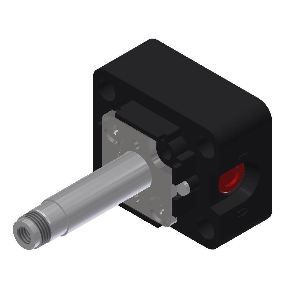
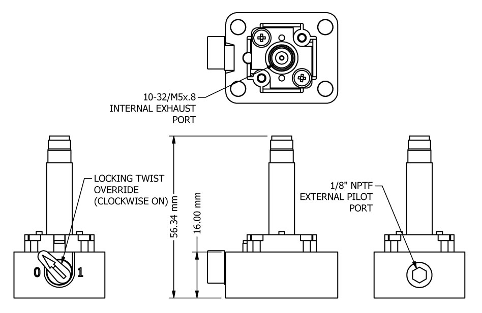
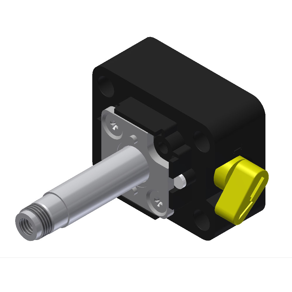
"Classic" Override - Locking Solenoid Twist
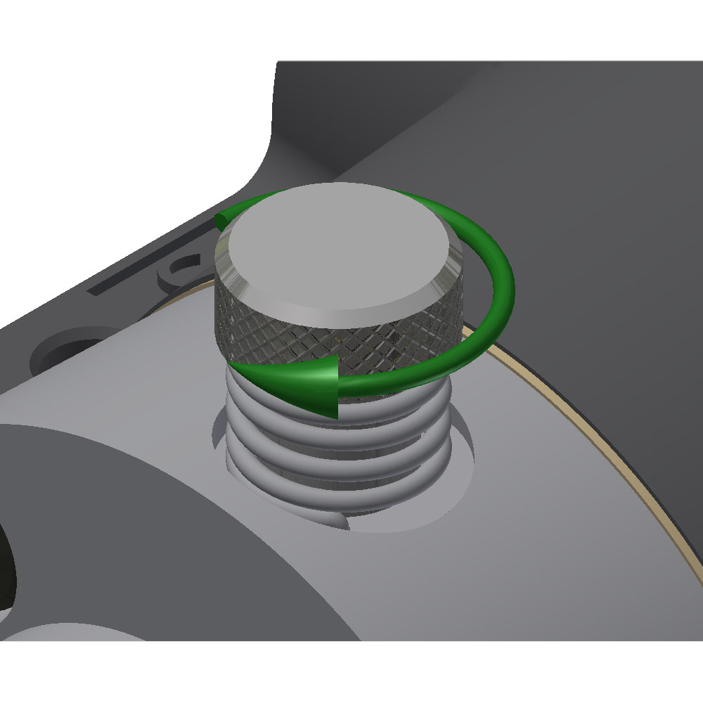
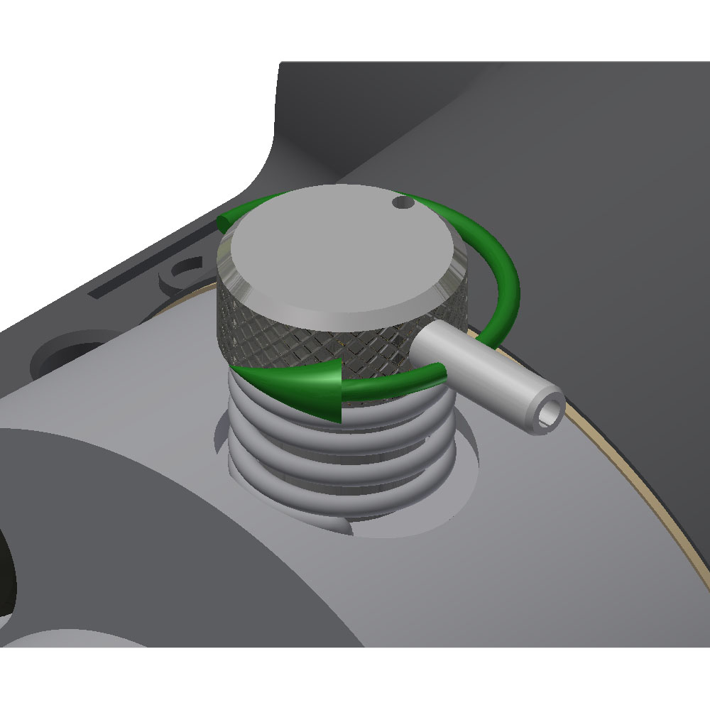
Manual override provides a method to shift the valve in case of an electrical failure or during proofing of the electrical control circuit. A knurled knob, operated by hand, physically lifts the poppet off its seat. Air pressure to the solenoid is required to shift the internal spool. The knob will remain either in the ON or OFF position. Twist the knob clockwise to lift the poppet.
"Classic" Override - Non-Locking Twist
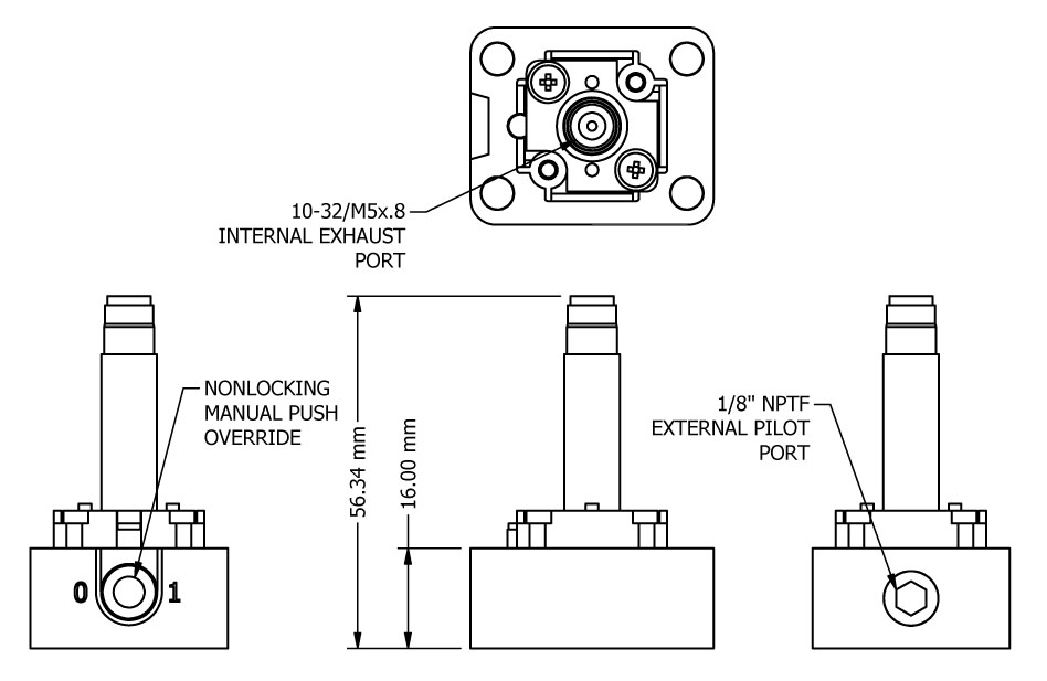
"Classic" Override - Non-Locking Push
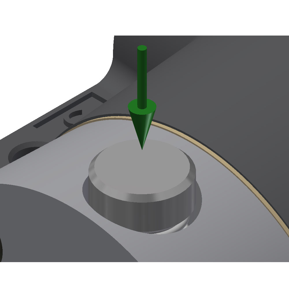
Manual override provides a method to shift the valve in case of an electrical failure or during proofing of the electrical control circuit. A push button, operated by hand, physically lifts the poppet off its seat. Air pressure to the solenoid is required to shift the internal spool. The button will only remain in the ON position while held, once released it will move back to the OFF position. Push down on the button to lift the poppet.
"Classic" High Pressure - 300 psi Solenoid Operator
High pressure solenoid operator allows up to 300 psi pilot pressure on the operator. Supply pressure can be either internal or external. Some valves can be rated for iternal pressures higher than the stated 250 psi. This must be requrested at time of order.
"E-Series" Coil - Standard
| Voltage | Pick-Up | Holding | Resistance | Spare Coil | |
|---|---|---|---|---|---|
| 24 volts, 50/60 Hz | 7.1 VA | 5.8 VA | 27.4 ohms | V-551-2 | 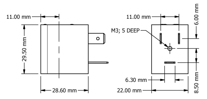 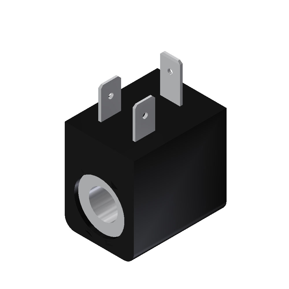  |
| 48 volts, 50/60 Hz | 7.7 VA | 6.2 VA | 97.9 ohms | V-551-3 | |
| 110 volts, 50 Hz, 120 volts, 60 Hz | 7.8 VA | 6.3 VA | 619 ohms | V-551-1 | |
| 240 volts, 50/60 Hz | 7.8 VA | 6.3 VA | 3400 ohms | V-551-4 | |
| 12 volts D-C | 4.6 Watts | 27.4 ohms | V-551-2 | ||
| 24 volts D-C | 4.8 Watts | 97.9 ohms | V-551-3 | ||
| 60 volts D-C | 4.3 Watts | 619 ohms | V-551-1 |
Ambient Temperature: -20°C to +50°C.
Relative Duty Cycle: 100% (continuous voltage).
Degree of Protection: IP65 with connector (IP67 possible with stem O-Rings).
Certifications: This coil carries the UL certificate of compliance both the standard and Canadian certification. A copy of the certification is available here. The rating only applies to the coil and not the entire valve.
Voltage Tolerance: ± 10%.
Resistance Tolerance: ± 8% at 20°C.
Insulation Class: F
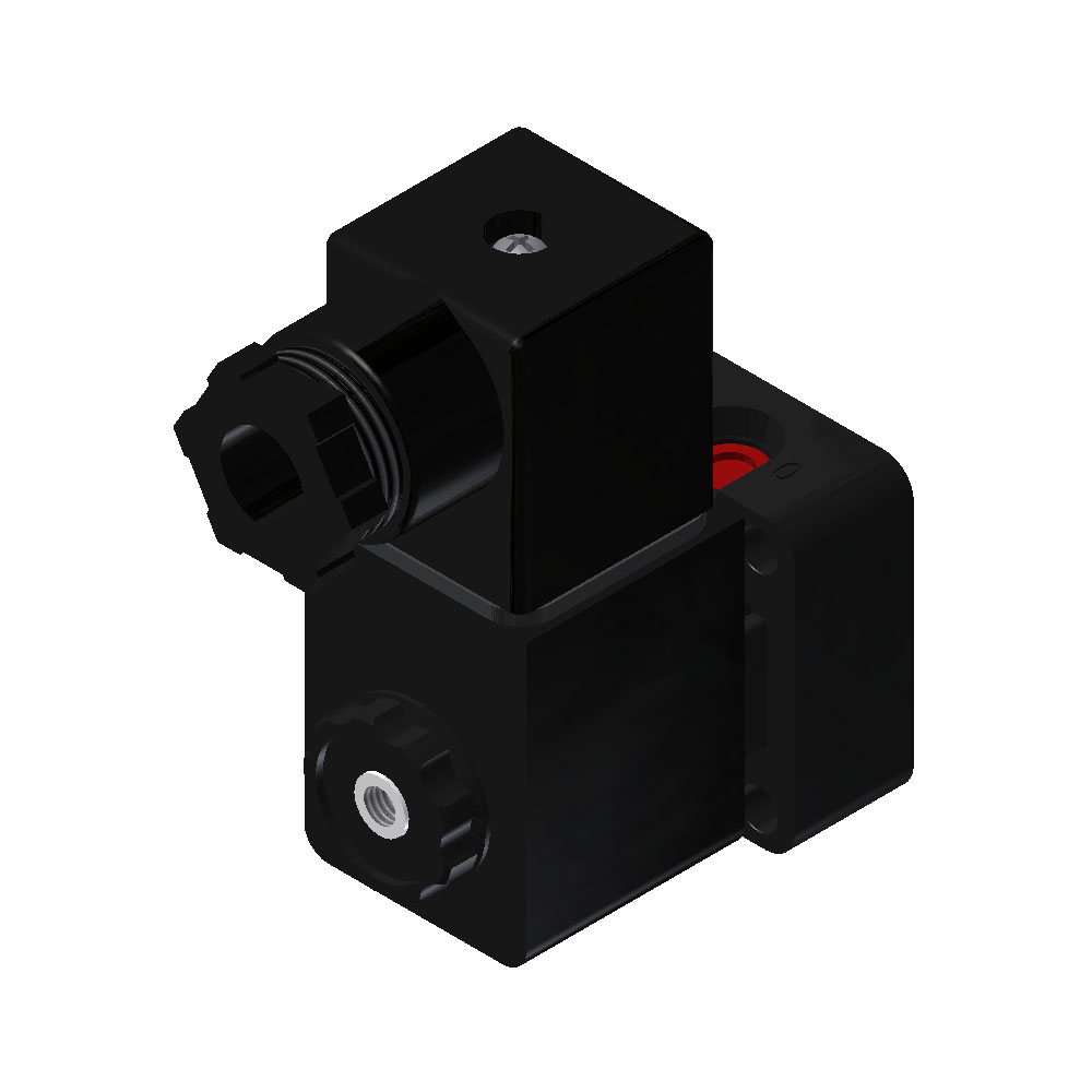
"E-Series" Coil - Option A - Intrinsically Safe
These operators are equipped with the standard V-562 nut but can be ordered with a V-567W bronze muffler nut (option L) or a V-562 side exhaust nut (option C).
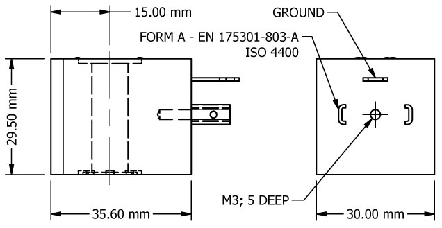
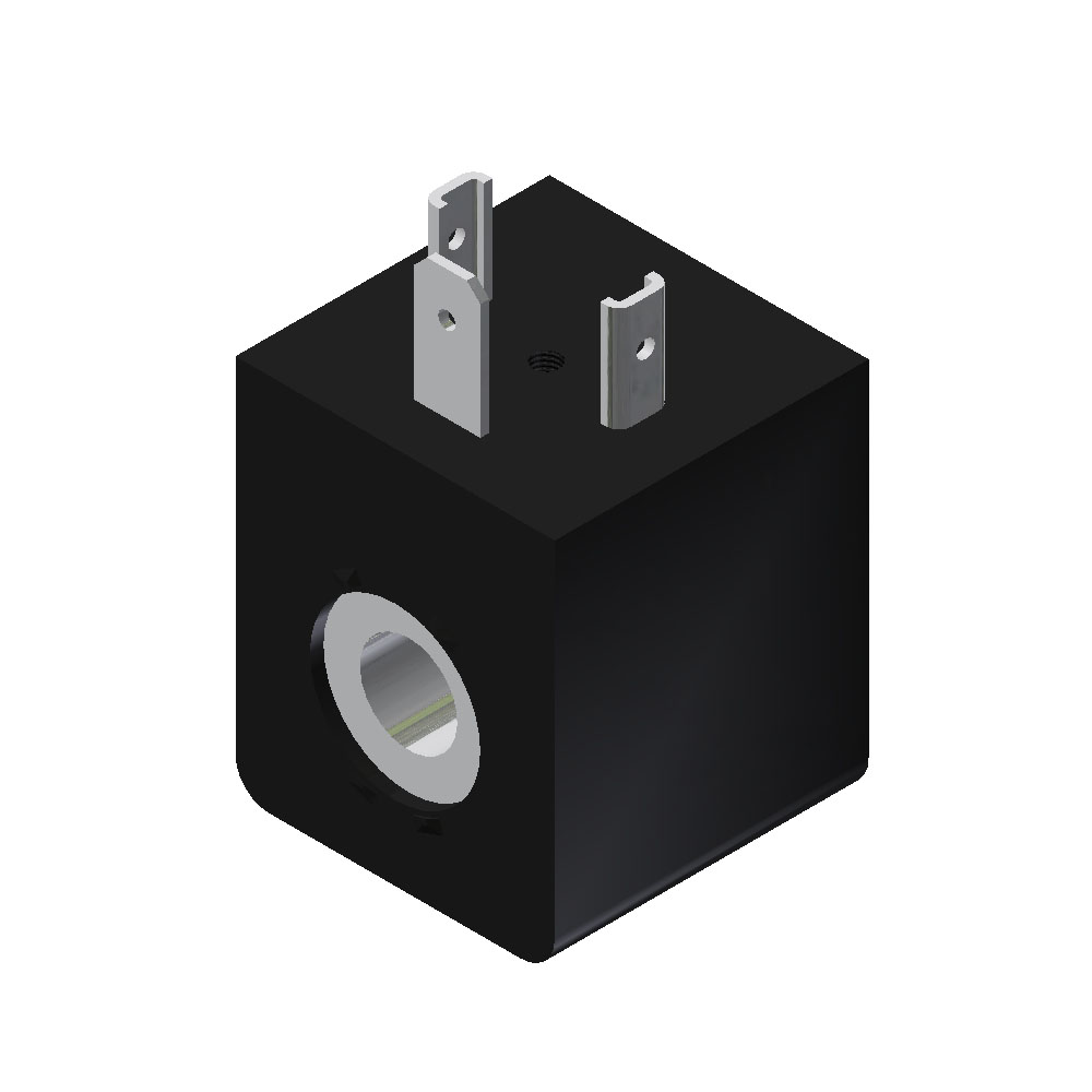
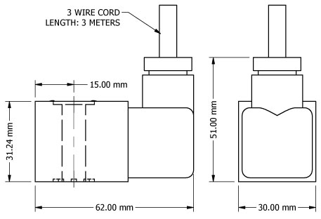
These 24 VDC coils are approved according to EN 50 020 respectively DIN VDE 0170/0171 part 5 for hazardous location. Class I, groups A, B, C and D; Class II, groups E, F and G; Class III. This coil is an ISO 4400 DIN style pin pattern. A non-indicator, cord grip style cap is provided. A copy of the certification is available here. An approved cap (included) must be used when connecting to an electrical source. The longer tab is the ground (earth). Either shorter tab can be connected to hot (+) and the other connected to neutral (-).
Molding Material: Thermoset resin.
Ambient Temperature: -20°C to +50°C.
Internal Diameter Orifice: 0.8mm
Relative Duty Cycle: 100% (continuous voltage).
Degree of Protection: IP65 with connector.
Certifications: This coil carries the following certificate of compliance. The rating only applies to the coil/operator and not the entire valve.
Insulation Class: F
Electrical Characteristics: 21.6 - 28 VDC
"E-Series" Intrinsically Safe Barrier
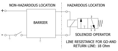
COMPATIBLE BARRIER MANUFACTURERS
Pepperl & Fuchs Inc. - Telephone (330) 425-3555 - FAX: (330) 425-4607
Pepperl+Fuchs, Inc., 1600 Enterprise Parkway, Twinsburg, Ohio 44087
E-mail: sales@us.pepperl-fuchs.com - www.pepperl-fuchs.com
Models: KFD2-SLS-EX2 and KFD2-SD-EX1.36
Eaton
Process Safety Automation Measurement
www.eaton.com/us/en-us/products/process-safety-automation-measurement/intrinsic-safety
Model: MTL5525
STAHL, INC - Telephone: (800) 782-4357
R. Stahl, Inc.
13259 N. Promenade Blvd, Stafford, TX 77477
E-Mail: sales.us@r-stahl.com - www.rstahl.com
Model: 9275/10-24-48-11s
"E-Series" Coil - Option H - High Temperature
Ambient Temperature: -20°C to +80°C.
Relative Duty Cycle: 100% (continuous voltage).
Degree of Protection: IP65 with connector.
Voltage Tolerance: ± 10%.
Resistance Tolerance: ± 8% at 20°C.
Insulation Class: H
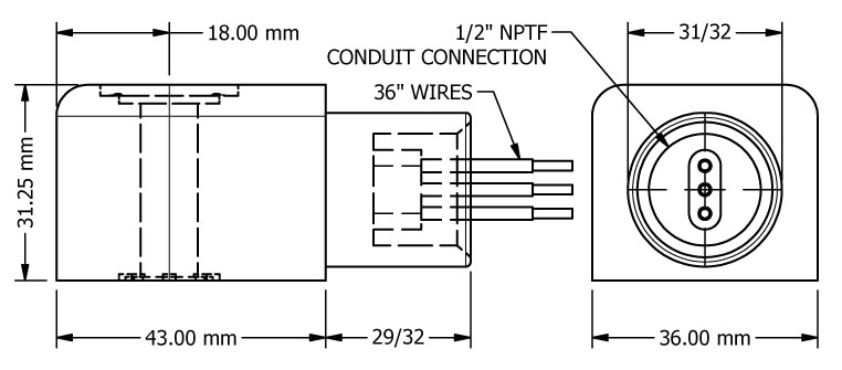
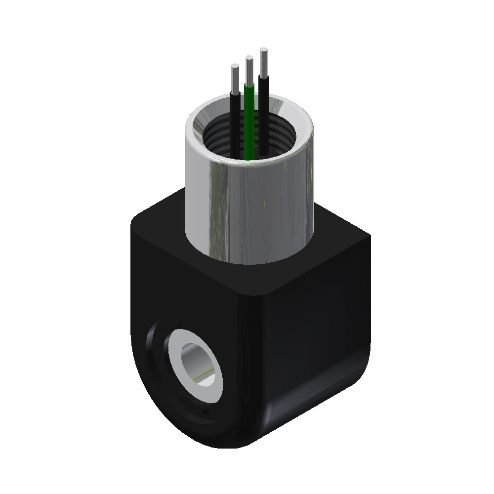
"E-Series" Coil - Option J - 1/2" Conduit Mold-Over
| Voltage | Pick-Up | Holding | Resistance | Spare Coil | |
|---|---|---|---|---|---|
| 24 volts, 60 Hz | 7.1 VA | 5.8 VA | 31.6 ohms | V-600-2 | 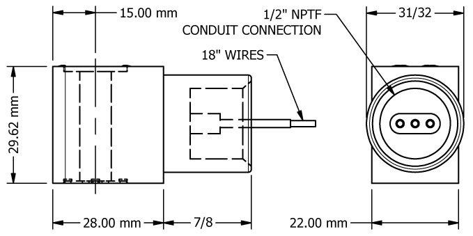 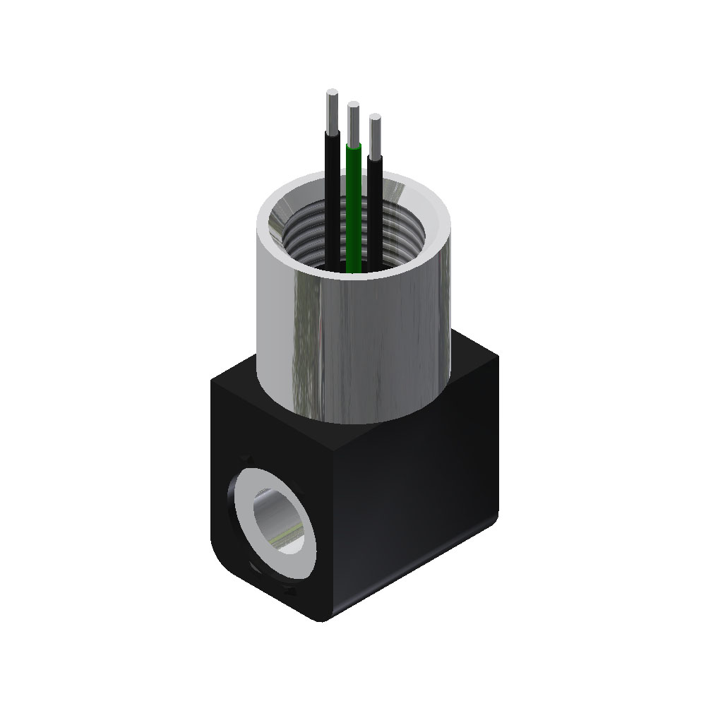   |
| 48 volts, 60 Hz | 7.7 VA | 6.2 VA | 121 ohms | V-600-3 | |
| 120 volts, 60 Hz | 7.8 VA | 6.3 VA | 820 ohms | V-600-1 | |
| 240 volts, 60 Hz | 7.8 VA | 6.3 VA | 3400 ohms | V-600-4 | |
| 12 volts D-C | 4.6 Watts | 31.6 ohms | V-600-2 | ||
| 24 volts D-C | 4.8 Watts | 121 ohms | V-600-3 | ||
| 60 volts D-C | 4.3 Watts | 820 ohms | V-600-1 |
Ambient Temperature: -20°C to +80°C.
Relative Duty Cycle: 100% (continuous voltage).
Degree of Protection: IP65.
Voltage Tolerance: ± 10%.
Resistance Tolerance: ± 8% at 20°C.
Insulation Class: F
"E-Series" Coil - Option M - 18" Flying Lead
| Voltage | Pick-Up | Holding | Resistance | Spare Coil | |
|---|---|---|---|---|---|
| 24 volts, 60 Hz | 7.1 VA | 5.8 VA | 27.4 ohms | V-569-2 | 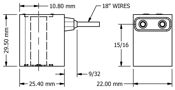 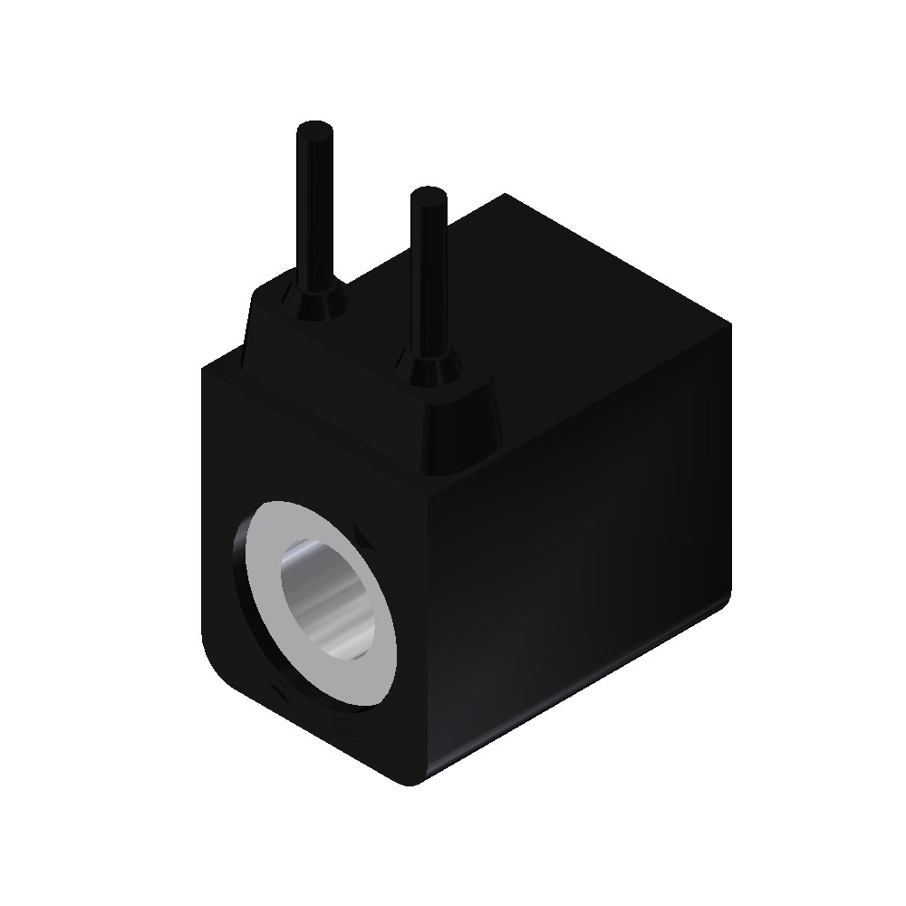   |
| 48 volts, 60 Hz | 7.7 VA | 6.2 VA | 97.9 ohms | V-569-3 | |
| 120 volts, 60 Hz | 7.8 VA | 6.3 VA | 619 ohms | V-569-1 | |
| 240 volts, 60 Hz | 7.8 VA | 6.3 VA | 3400 ohms | V-569-4 | |
| 12 volts D-C | 4.6 Watts | 27.4 ohms | V-569-2 | ||
| 24 volts D-C | 4.8 Watts | 97.9 ohms | V-569-3 | ||
| 60 volts D-C | 4.3 Watts | 619 ohms | V-569-1 |
Ambient Temperature: -20°C to +50°C.
Relative Duty Cycle: 100% (continuous voltage).
Degree of Protection: IP65 (IP67 possible with stem O-Rings).
Certifications: This coil carries the UL certificate of compliance both the standard and Canadian certification. A copy of the certification is available here. The rating only applies to the coil and not the entire valve.
Voltage Tolerance: ± 10%.
Resistance Tolerance: ± 8% at 20°C.
Insulation Class: F
"E-Series" Coil - Option T - ATEX
| Voltage | Pick-Up | Holding | Resistance | Spare Coil |
|---|---|---|---|---|
| 24 volts D-C | 0.136 amps | 177 ohms | V-612-3 |
Ambient Temperature: -20°C to +50°C.
Relative Duty Cycle: 100% (continuous voltage).
Degree of Protection: IP65 (IP67 possible with stem O-Rings).
Certifications: This coil carries the ATEX/IEC certificate of conformity. A copy of the certification is available here. The rating only applies to the coil and not the entire valve.
Voltage Tolerance: ± 10%.
Resistance Tolerance: ± 8% at 20°C.
Insulation Class: H
"E-Series" Coil - Option X - Explosion Proof
Conduit Material: on V-593-1 thru -3, stainless steel. On V-593-4, zinc plated.
Ambient Temperature: -20°C to +60°C.
Relative Duty Cycle: 100% (continuous voltage).
Degree of Protection: IP65 with connector (IP67 possible with accessories).
Certifications: This coil carries both a FM and CSA approval rating; CSA CLASS 2258 02, process control equipment for hazardous locations; FM CLASS 3600, 3611, 3615, 3810, hazardous (classified) location electrical equipment. A copy of the certification is available here. The rating only applies to the coil and not the entire valve.
Voltage Tolerance: ± 10%.
Resistance Tolerance: ± 8% at 20°C.
Insulation Class: H
Commonly Asked Questions
A: Yes. If equipment has been approved for use in a Division 1 hazardous location, it can be used in a Division 2 hazardous location, providing it is in the same class and group.
A: No. Equipment used in Class I and Class II hazardous locations are made for different purposes. Equipment approved for Class I hazardous locations must contain an internal explosion, while Class II approved equipment must seal out dust. They are not interchangeable.
"E-Series" Operator - Standard
Molding Material: Thermoplastic.
Ambient Temperature: -20°C to +50°C.
Internal Diameter Orifice: 1.3mm
"E-Series" Operator - Twist Style Locking Override
Molding Material: Thermoplastic.
Ambient Temperature: -20°C to +50°C.
Internal Diameter Orifice: 1.3mm
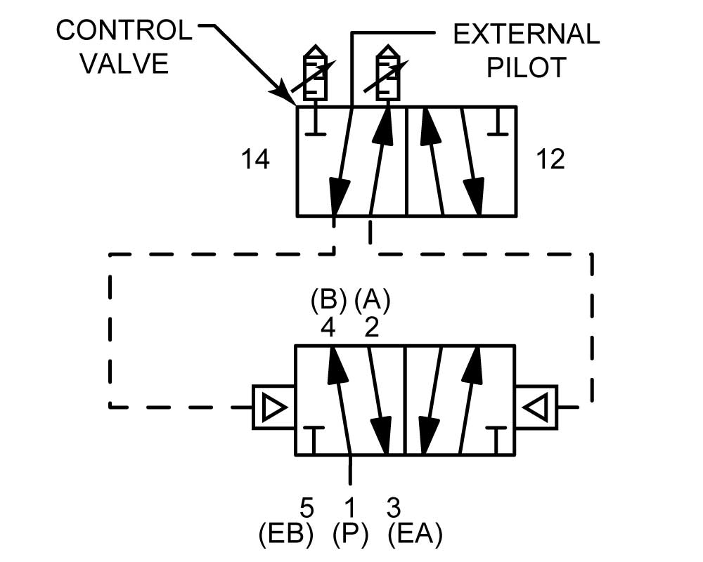
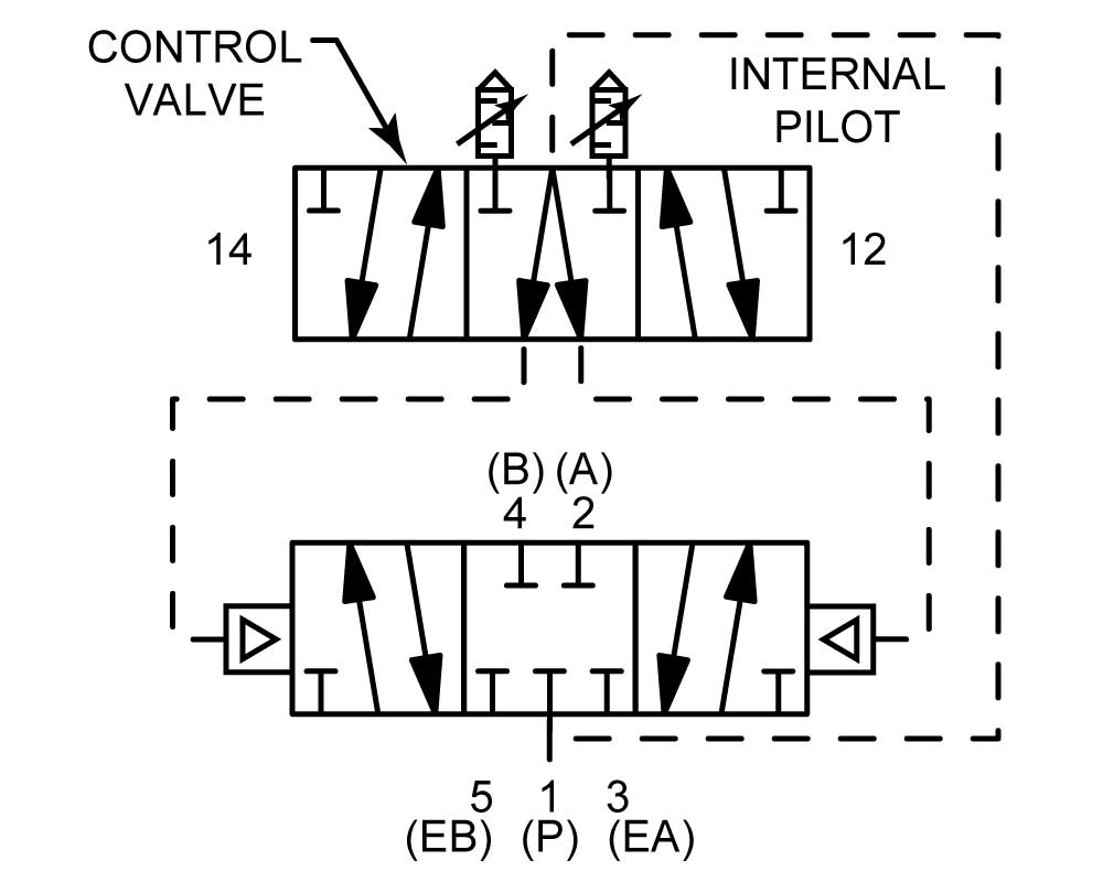
General - 1-1/2" & 2" Valve Operation
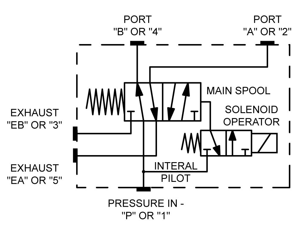
Normal assembly of all standard 1-1/2" & 2" valves is for internal pilot operation, in which the air pressure for shifting the large spool is internally tapped off the valve inlet. If the main spool is to handle pressures lower than 50 PSI or more than 150 PSI on
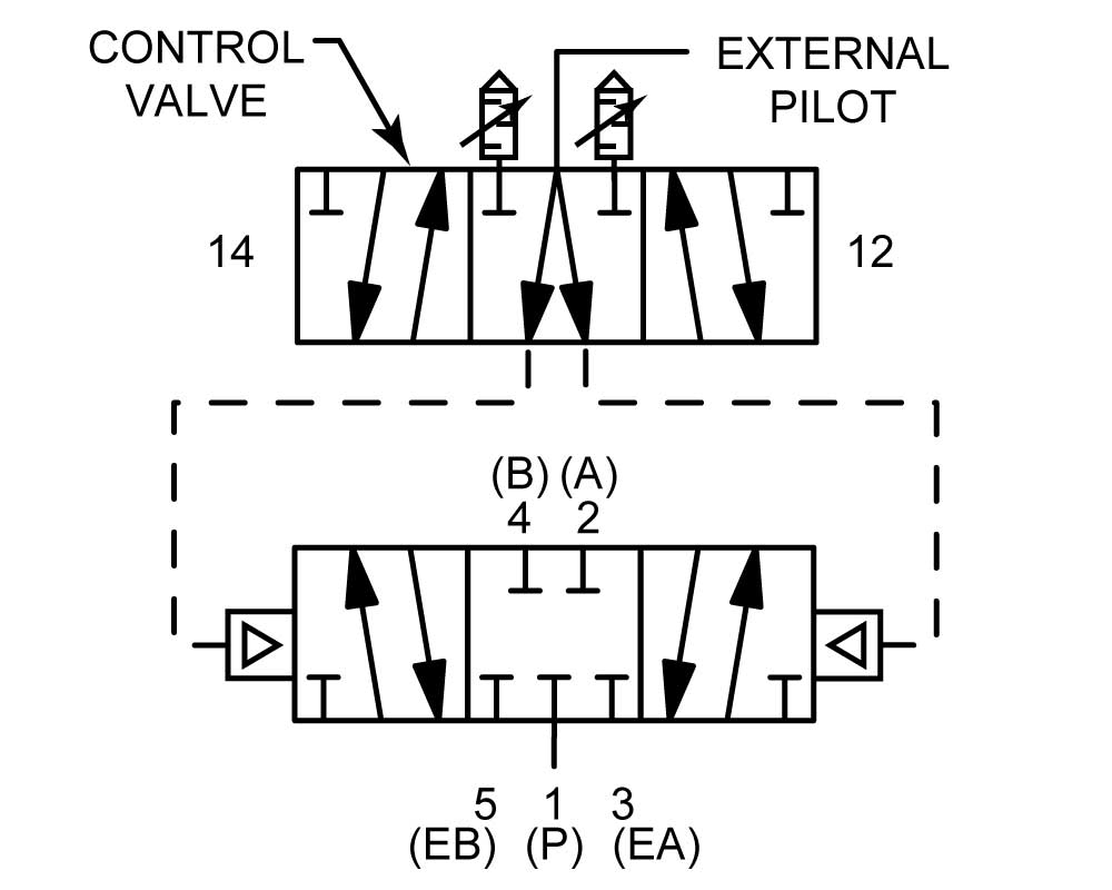
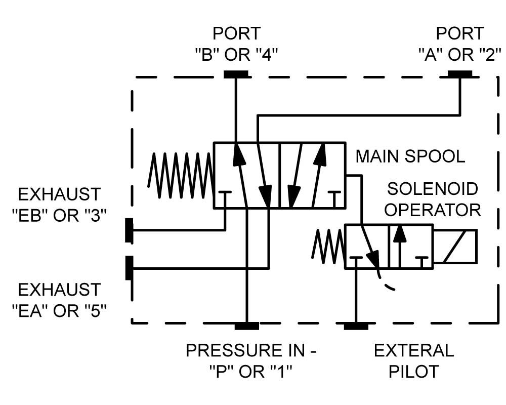
Normal assembly of all standard 1-1/2" & 2" valves is for internal pilot operation, in which the air pressure for shifting the large spool is internally tapped off the valve inlet. If the main spool is to handle pressures lower than 50 PSI or more than 150 PSI on solenoid models or from 50 to 250 psi on all other models, the valve should be factory ordered for "external pilot operation" by adding suffix "Z" after the regular model number. Or, the valve can easily be converted in the field to external piloting as described below. This pressure limitation applies to all 1-1/2" and 2" manual lever, solenoid, pilot or differential pilot valves.
Conversion to External Piloting: Remove the entire control valve from the main body and lay it aside. Install a 1/16"-27 NPT pipe plug in the treaded hole uncovered in the body mounting pad. Re-mount the control valve in the same orientation as before. Connect a pilot pressure air source (50 to 150 PSI on solenoid models and 50 to 250 psi on all other models) to the 1/4" NPTF external pilot port. This port is located on the side and near the top of the main body and stamped "EXT P", on the side opposite the MFC flow controls.
General - Converting to "EXTERNAL PILOT" Operation
- On 1/4" and 3/8" models (with solenoid assemblies mounted on the ends), remove 4 screws holding the solenoid structure to the main body and remove the entire solenoid assembly. Rotate the entire solenoid assembly 180° and re-mount on the body. Connect a source of external pilot pressure, 50 to 150 psi, to the ext. pilot port of each solenoid structure. On double solenoid valves, both solenoids must be modified in this manner, and the source of external pilot pressure must be connected to the pilot port on both structures.
- On 1/4" and 3/8" models (with solenoid assemblies piggy-backed on top of valve), remove 4 screws holding the piggy back structure to the main body and remove the entire assembly. Leave gasket as orientated on the main body and rotate the piggy back assembly 180° and re-mount on the body. Connect a source of external pilot pressure, 50 to 150 psi, to the ext. pilot port of piggy back structure.
- On 1/2", 3/4" and 1" models, take out 4 screws and remove end cap assembly from end of valve body. Rotate gasket with the end cap assembly 90° in either direction. This will block the internal pilot passages. Connect a source of pilot pressure, 50 to 150 psi, to the 1/8" NPT pilot port on the side of the end cap structure. On double solenoid valves, both solenoids must be modified in this manner, and the source of external pilot pressure must be connected to the pilot port on both structures.
- On 1-1/2" and 2", remove entire pilot valve assembly on top and install a 1/16"-27 pipe plug in the threaded hole uncovered in the main body. Re-mount the pilot valve and connect an external source of pilot pressure, 50 to 150 psi, into the ext. pilot port on the main body.
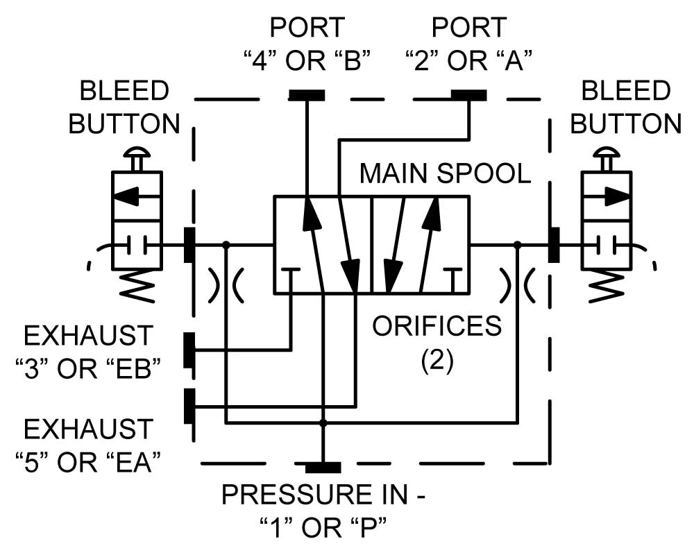
General - Differential Pilot Operation
A minimum of 25 psi is required for reliable shifting of non-spring models. Minimum pressure for spring offset and 3 position models is 50 psi. They will not operate correctly on compressed air lines of less than 25 psi. They are not suitable for liquids. By careful design they can be built in a 3 position, spring centered configuration.
The bleed buttons can be removed from the valve body and mounted on 1/4" hose or tube extensions for shifting the valve from a few feet away. Any other 2-way normally closed (N.C.) valve, manual, cam or solenoid valve can be substituted for either or both bleed buttons.
General - Installation & Maintenance
Bulletin A-113: Operating & Maintenance Instructions.
Installation: Valve Fitting Installation.
 WARNING:These products can expose you to chemicals which is(are) known to the State of California to cause cancer or reproductive harm. For more information, go to www.P65Warnings.ca.gov. Contact us for specific chemicals or materials used in a product.
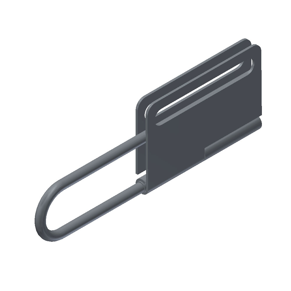
General - LO23/Lock-out Hasp
Lock-out hasp, part number LO23 is required when you want to use multiple locks. Size: 6-3/4" x 2-3/8", manufactured out of steel. The shackle diameter is 1/4".
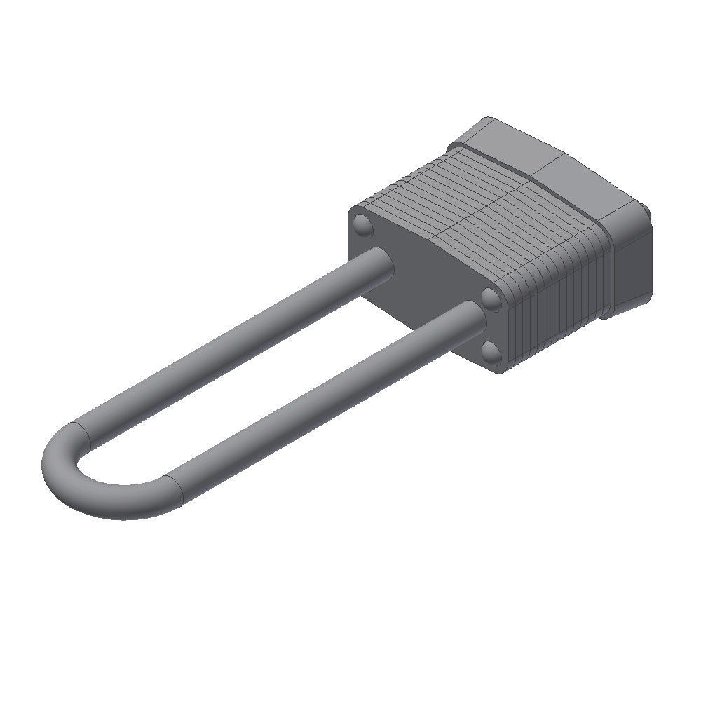
General - 7LJ Masterlock
7LJKAP Masterlock can be used to lock the movement of the handle. The shackle diameter is 3/16".
General - Lubrication, Standard
The shelf life of Magnalube-G regularly lasts for 10+ year intervals in closed packaging due to the extremely long operating life of the Elastomer-PTFE gelling agent and premium parafiinic mineral base oil. If the valve is stored for over 2 years, then a small reapplication of grease is suggested.
Magnalube-G Technical Document
Magnalube-G MSDS Document
An alternative grease for low temperature application, refer to Dow-55 grease.
General - Lubrication, DOW-55
To specify the use of Dow-55 grease, use the suffix "W" to the end of the valve part number. This should be the last letter in the part number structure.
If the valve is stored for over 2 years, then a small reapplication of grease is suggested.
Molykote-55 Technical Document
Molykote-55 MSDS Document
The standard grease for most applications, refer to Magnalube-G grease.
General - O-Ring Information
| Dash No. | O-ring Description | Temperature Rating |
|---|---|---|
| -2 | Silicone | -80°F to 400°F |
| -3 | Viton for most aromatic gases | -20°F to 400°F, 600°F for short time |
| -7 | Urethane, 70 Durometer | -65°F to 200°F |
| -9 | Buna-N | -40°F to 250°F |
General - O-Ring Materials
| Dash No. | Material | Description |
|---|---|---|
| -2 | Silicon | Silicone is a semi-organic elastomer with outstanding resistance to extremes of temperature. Specially compounded, it can provide reliable service at temperatures as low as -80°F (-60°C) to as high as 400°F (205°C) continuously. Silicone also has good resistance to compression set. Low physical strength and abrasion resistance combined with high friction limit silicone to static seals. Silicone is used primarily for dry heat static seals. Although it swells considerably in petroleum lubricants, this is not detrimental in most static sealing applications. Advantages:
|
| -3 | Viton | Fluorocarbon combines resistance to a broader range of chemicals than any of the other elastomers. It constitutes the closest available approach to the universal O-ring elastomer. Although most fluorocarbon compounds become quite hard at temperatures below -20°F (-29°C), they do not easily fracture, so they are serviceable at much lower temperatures. Fluorocarbon compounds provide a continuous 400°F (205°C) high temperature capability. Advantages:
|
| -7 | Urethane | Urethane material has outstanding wear and tear resistance, very low compression set ensuring maximum service life. Due to exceptional material strengths, O-Rings do not require Back-Up Rings when operating at high temperatures and/or pressures. Serviceable temperature range of -65°F to 200°F (-54°C to 93°C). Advantages:
|
| -9 | Buna-N | Nitrite is the most widely used elastomer in the seal Industry. The popularity of nitrite is due to its excellent resistance to petroleum products and its ability to be compounded for service over a temperature range of -40°F to 250°F (-40°C to 121°C). Nitrite is a copolymer of butadiene and acrylonitrile. Variation in proportions of these polymers is possible to accommodate specific requirements, an increase in acrylonitrile content increases resistance to heat plus petroleum base oils and fuels but decreases low temperature flexibility. Military AN and MS O-ring specifications require nitrite compounds with low acrylonitrile content to insure low temperature performance. Nitrite provides excellent compression set, tear, and abrasion resistance. The major limiting properties of nitrite are its poor ozone and weather resistance and moderate heat resistance. Advantages:
|
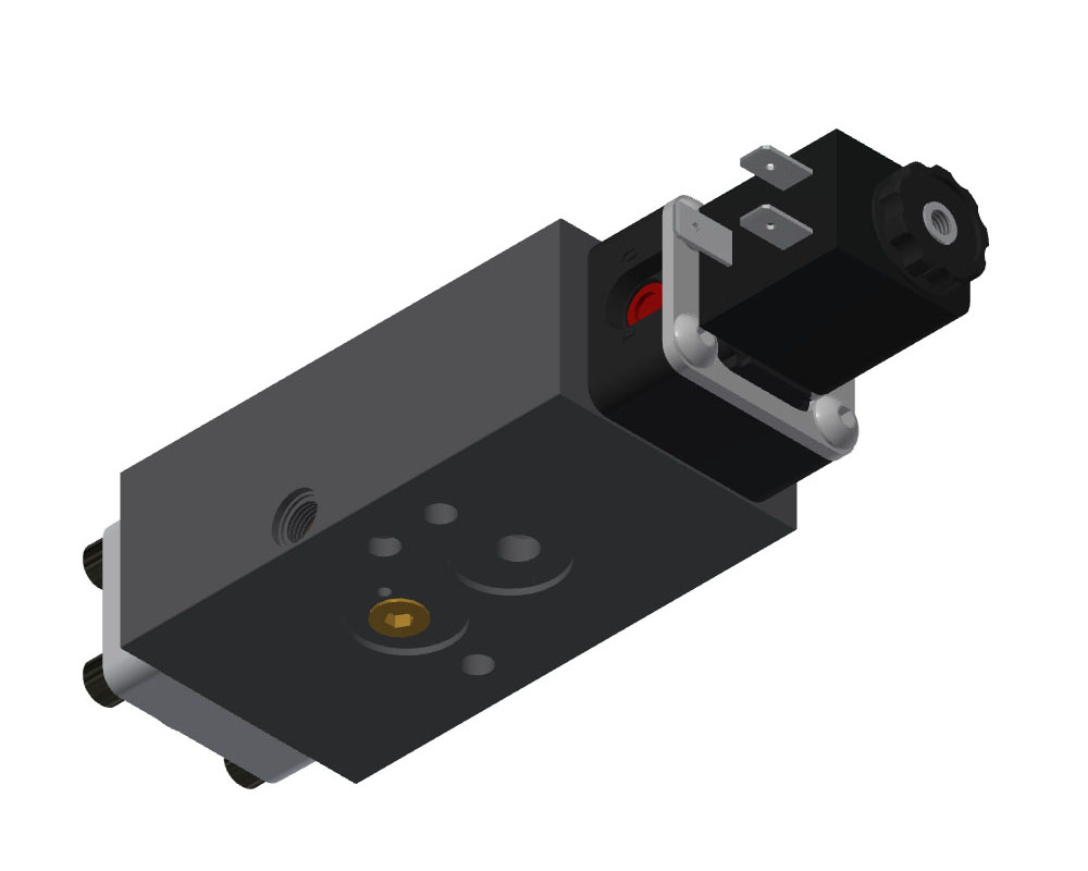
General - Solenoid Valve Operation
Basic Operation:
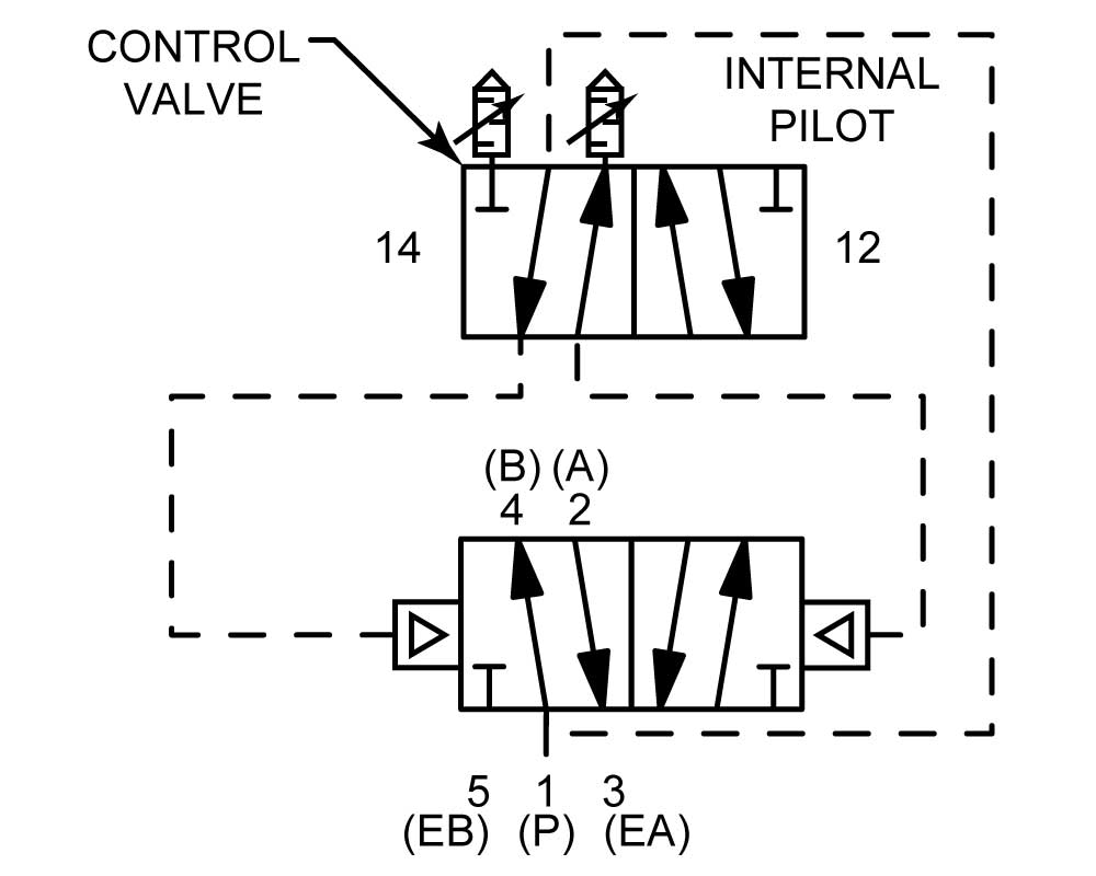
When the coil is supplied with the correct power, a magnetic field is generated that pulls in a plunger. The plunger directs the inlet of gas to the end of the internal spool. At the same time, the solenoid exhaust through the stem is blocked, preventing the escape of gas and allowing pressure to build. The increase in the pressure on the end of the spool will shift the spool. Pressure of 25 psi for non-spring models and 50 psi for spring return or spring centered models is required for reliable spool shift (150 psi maximum). When the coil is de-energized, the plunger is returned to position via an internal spring which blocks the inlet of gas to the internal spool. At the same time, the solenoid exhaust is opened and the pressure at the end of the internal spool is allowed to exhaust.
The solenoid can be used as a simple 3-way valve that directs a gas source to the end of the spool or allows the gas from the internal spool to vent. The solenoid vent can be plumbed for direction of exhaust gases.
The return shift of the internal spool is controlled either by a spring, second solenoid, or various mechanical or piloted options.
The inlet of gas to shift the spool can be derived from either internally or externally supplied gas.
Additional Considerations:
- If the solenoid exhaust is blocked, thus preventing the reduction of pressure of the internal spool, the valve may not return or function properly.
- The exhaust of the solenoid can be pressurized to shift the internal spool, but caution must be used so adequate pressure differentials between the end chambers of the internal spool will allow the shifting of the internal spool. Testing must be performed to assure correct valve operation.
- Do not energize the coil while it is not on the solenoid stem. This will cause the coil to burn up and no longer create the needed magnetic field.
- Higher power then what the coil is rated for can be applied for short periods. This may however reduce the life span of the coil.
- When bench testing of internally piloted valves, adequate back pressure on the operating ports is required to allow sufficient pressure to shift the internal spool.
Mounting - Inline or Side Port Connections
Mounting - Bottom Port Connections
Mounting - Namur
Usage - 3 Way
A 3-way application is typically a cylinder that is returned by an internal spring. Only air to extend the cylinder is required.
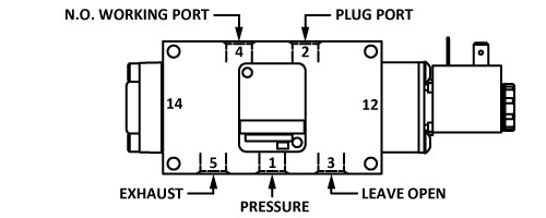 3-WAY N.O. APPLICATION
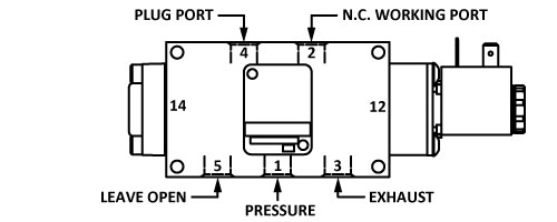 3-WAY N.C. APPLICATION
Usage - 3 Way - Namur Only
Usage - 4 Way
A 4-way application is one using one inlet pressure that is directed to two separate ports. When one port is pressurized, the other port is directed to an exhaust port. The most typical applications for a 4-way valve are the control of a cylinder or air motor.
All valves are tested at the factory for 4-way service. If a port other than port 1 is pressurized, inform the factory and additional testing will be performed.
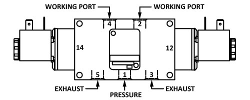 4-WAY APPLICATION
Usage - 5 Way
A 5-way application is one using two inlet pressure levels or in which inlet pressure is derived from two different sources for use in the same circuit. Another type of 5-way application is for conserving air on the return stroke of double-acting cylinders.
Standard AAA soft seal valves may be ordered for 5-way service with these exceptions: Solenoid valves must be re-connected to use an external source of 50 PSI to 150 PSI pilot pressure. Stack valve sections and differential pilot valves cannot be used for 5-way service.
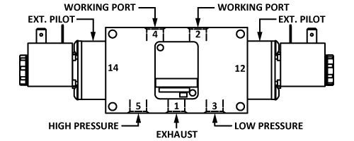
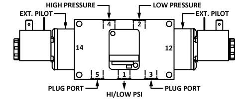 5-WAY APPLICATIONS
Flow Pattern - "Classic" Solenoid Valves
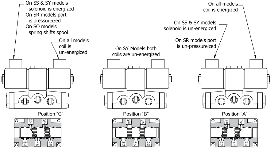
1/4" through 1":When a solenoid is energized causing the internal spool to shift, port 1 will connect to the port closest to the energized coil (ports 2 or 4). The furthest port will connect to the appropriate exhaust port (ports 3 or 5).
1-1/2" and 2":These larger valves use a "Piggy-Back" valve mounted to the top of the larger valve. The flow through the larger valve is the same as above.
Reversing Valve Operators
Understanding Valve Numbers
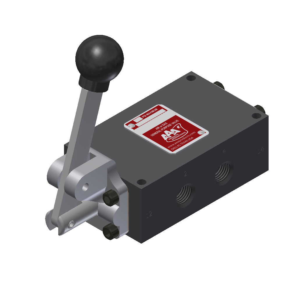
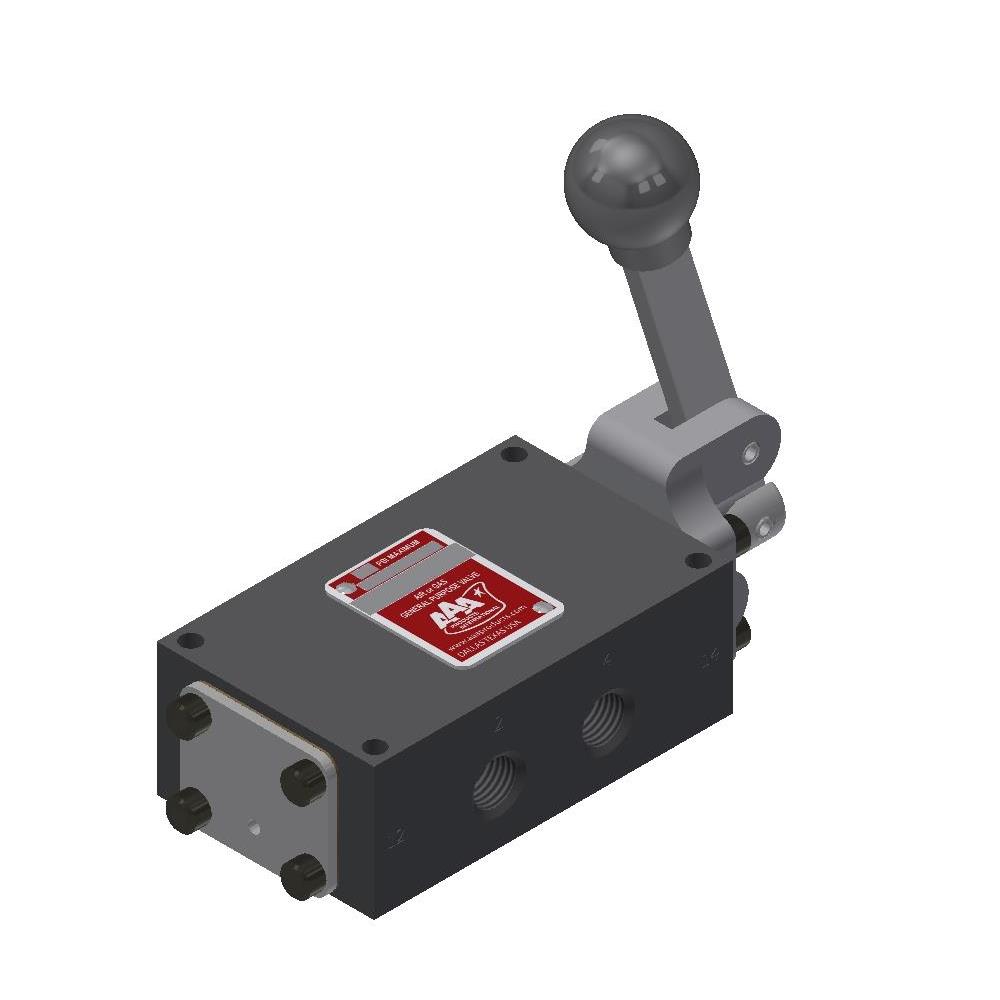
AAA valves use a simplified model code which calls out the most important characteristics with a minimum of coding. In the example, model SY3G is a double solenoid valve, 3/8" size, spring centered spool, float center type.
The first two letters in the code (SY) designate the type of operator on the left and right ends respectively when viewing toward the side with the "2 or A" and "4 or B" ports. The numeral (3) gives valve size in 8ths of an inch. This completes the model code for many valves. If, however, additional features are desired, one or more suffix letters can be added.
 | |||
| Valve Operators | Size | Typical Options | |
| C = Cam E = Friction Position F = Foot Pedal G* = Direct Pilot H = Manual Lever K = Palm Button O = Spring Offset | P = Piston R = Pilot S = Solenoid T = Treadle Y = Spring Centering D (in 1st pos.) = Bleeder D (in 2nd pos.) = Detent | 2 = 1/4" 3 = 3/8" 4 = 1/2" 6 = 3/4" 8 = 1" 12 = 1-1/2" 16 = 2" | D = Regenerative Spool Type G = Float Center Spool Type P = Subplate Mounting Q = 2-Position Detent X = Explosion Proof Operator Z = External Pilot Operation Others Availible. |
| *Special prefix for 1-1/2" and 2" air valves to designate valve body only, without a piggy back operator. | |||
All Solenoid Valves: We have changed our standard solenoid assembly to a new PLC friendly solenoid. To differentiate this style from our "Classic" solenoid valves, please use a prefix of "E" to all new solenoid valves. (E.g.; on SO2 to specify new solenoid style use ESO2).
Stack Series Valves: B-Series valves are similar in construction to the 1/4" & 3/8" side ported valves. B-Series are only available in 1/4" & 3/8" NPTF port sizes. To order a 1/4" manual lever valve, spring return in a stack valve you would add the prefix "B" to the part number (e.g. BHO2). On ESO2 with the new solenoid style use EBSO2 to denote stack valve.
Namur Series Valves: N-Series valves are similar in construction to the 1/4" & 3/8" side ported valves. N-Series are only available in 1/4" NPTF port sizes. To order a 1/4" solenoid valve, spring return in a Namur valve you would add the prefix "N" to the part number (e.g.; NSO2). Namur valves are only available with the new selnoid style, so the prefix "E" is omitted.
Brass Valves: The prefix "Z" denotes a brass 1/4" or 3/8" side ported body. Some valves and options are unavailble in brass. Consult factory for available options.
Dash: The suffix of a "-" then a number denotes body - O-Ring material. (E.g.; The part number SO3-9, would specify (-9) Buna-N material for the body O-Rings. For O-Ring materials and valid dash numbers see O-Rings.
W Suffix: The suffix of "W" denotes the optional use of DOW-55 grease. The standard grease is Magnalube-G. For some low temperature applications it is recommended to use DOW-55.
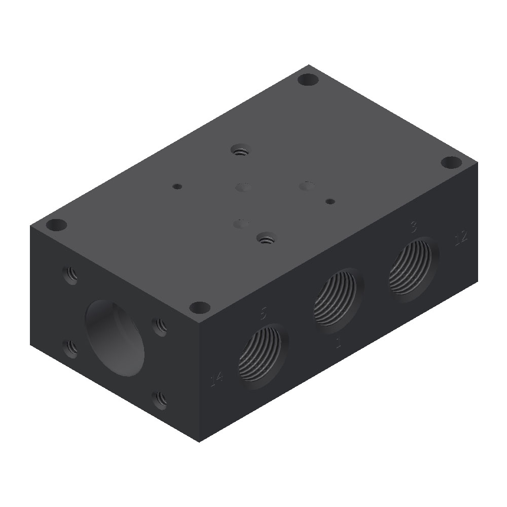
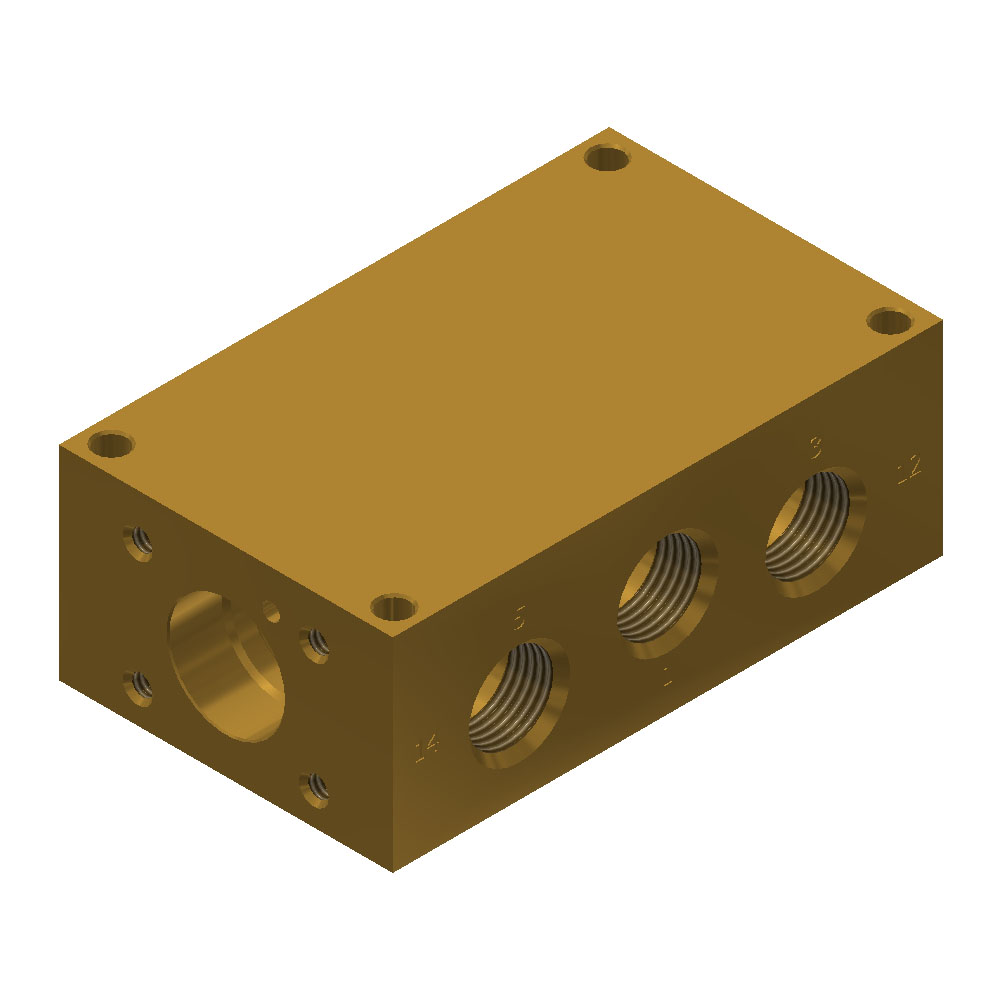
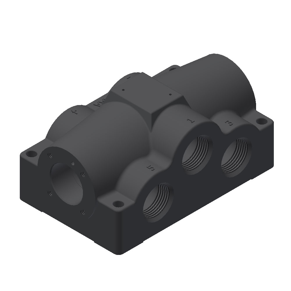
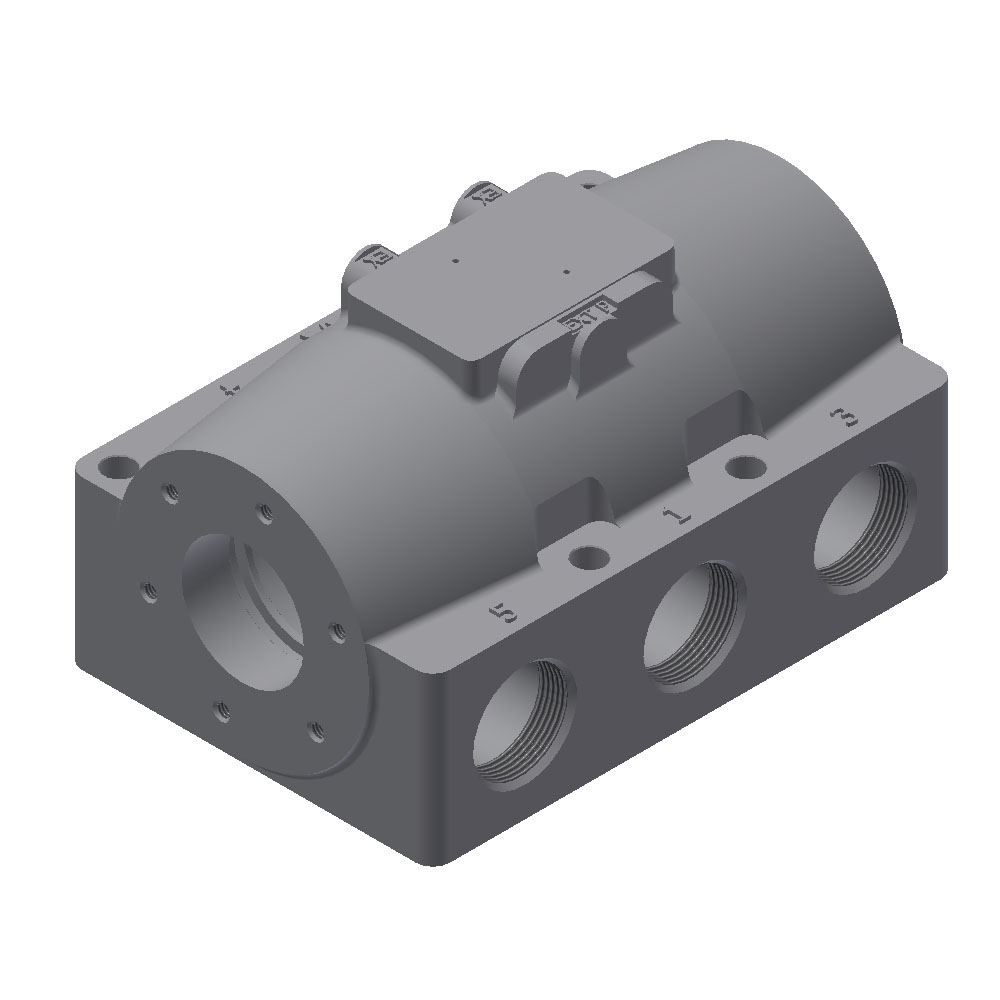
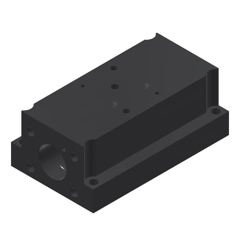
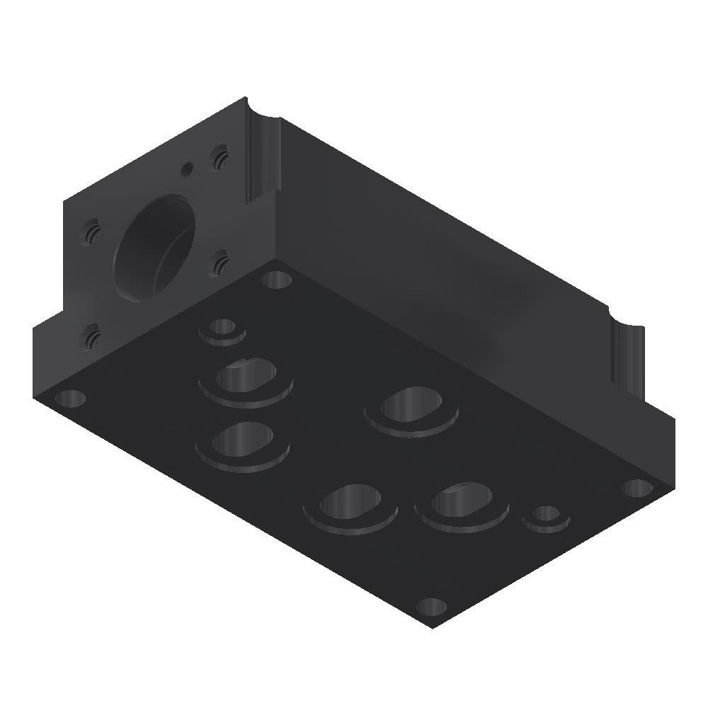
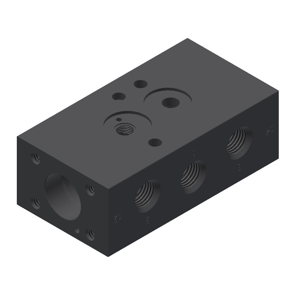
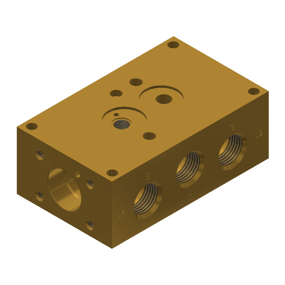
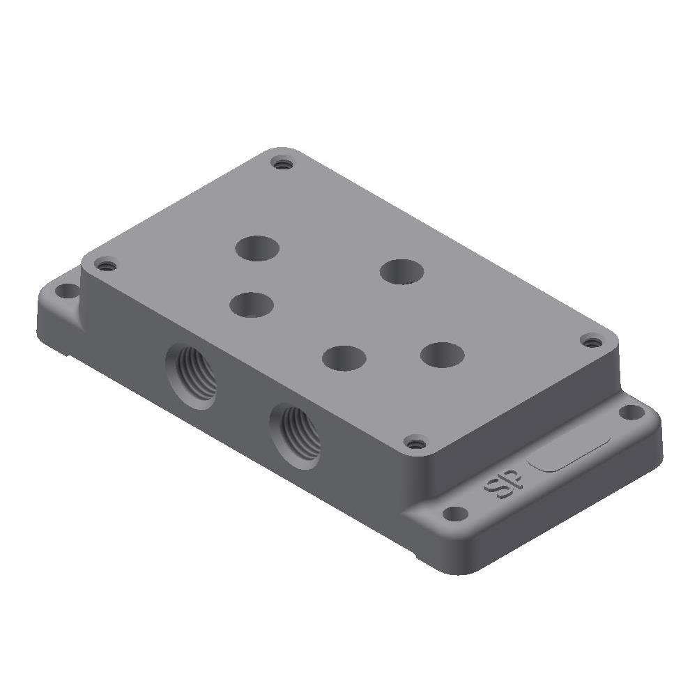
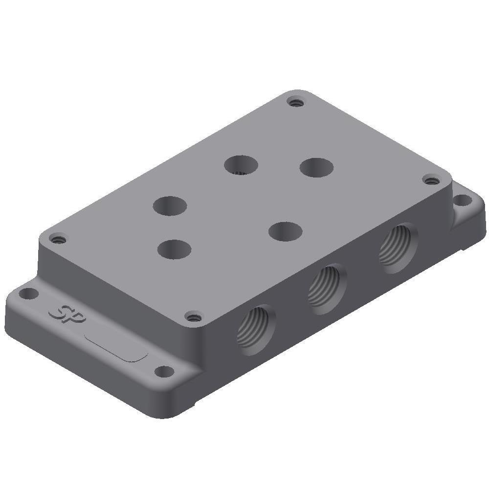
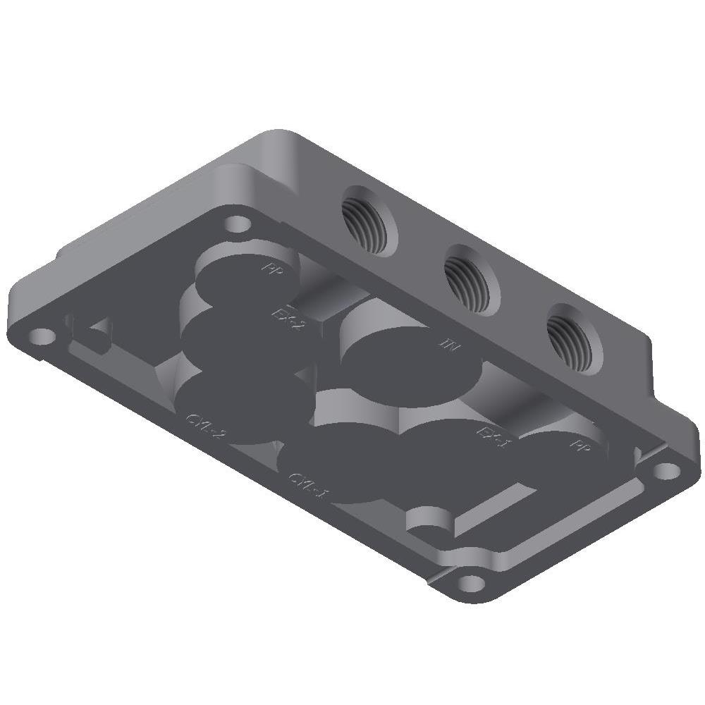
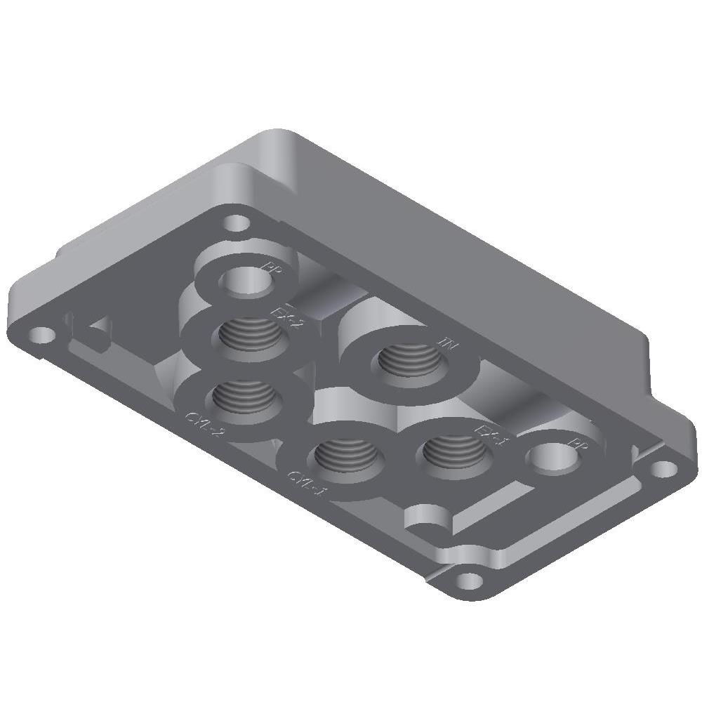
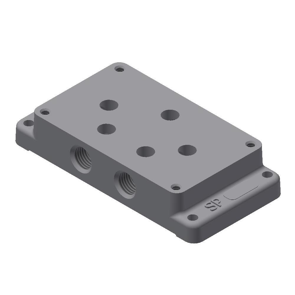
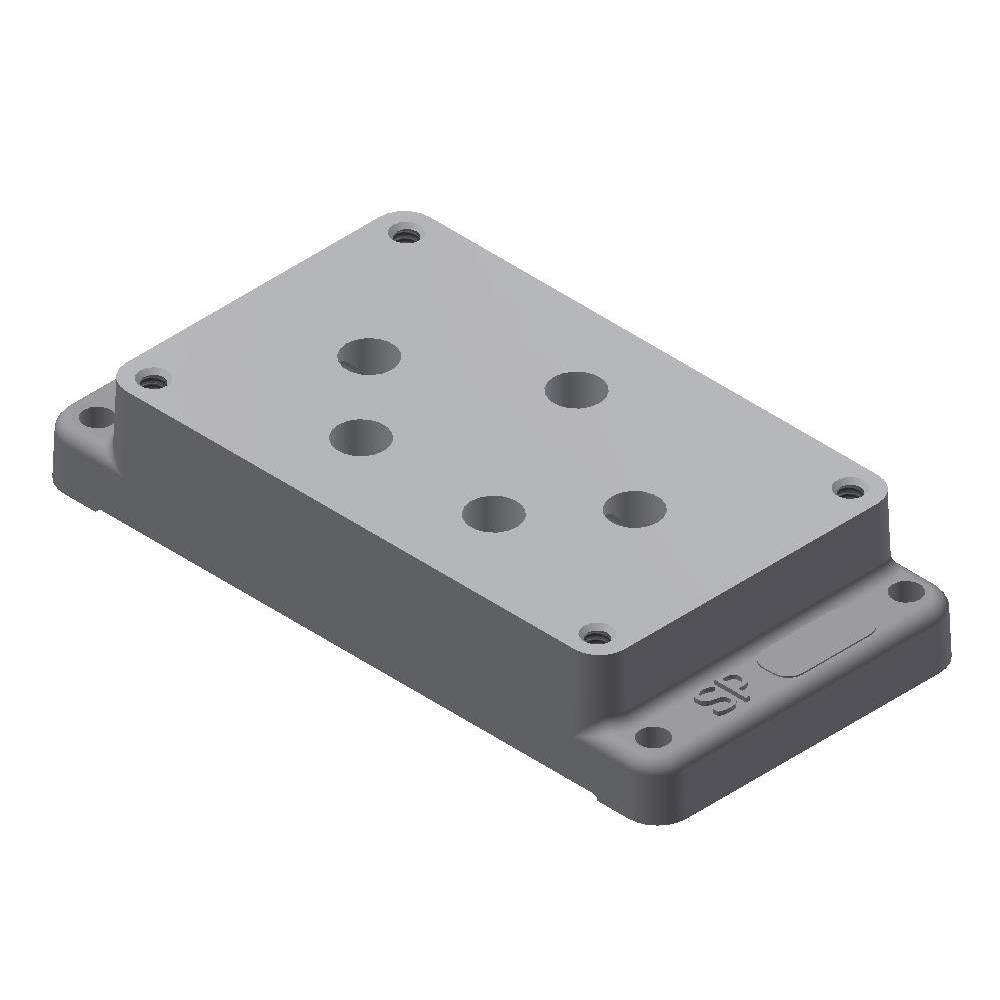
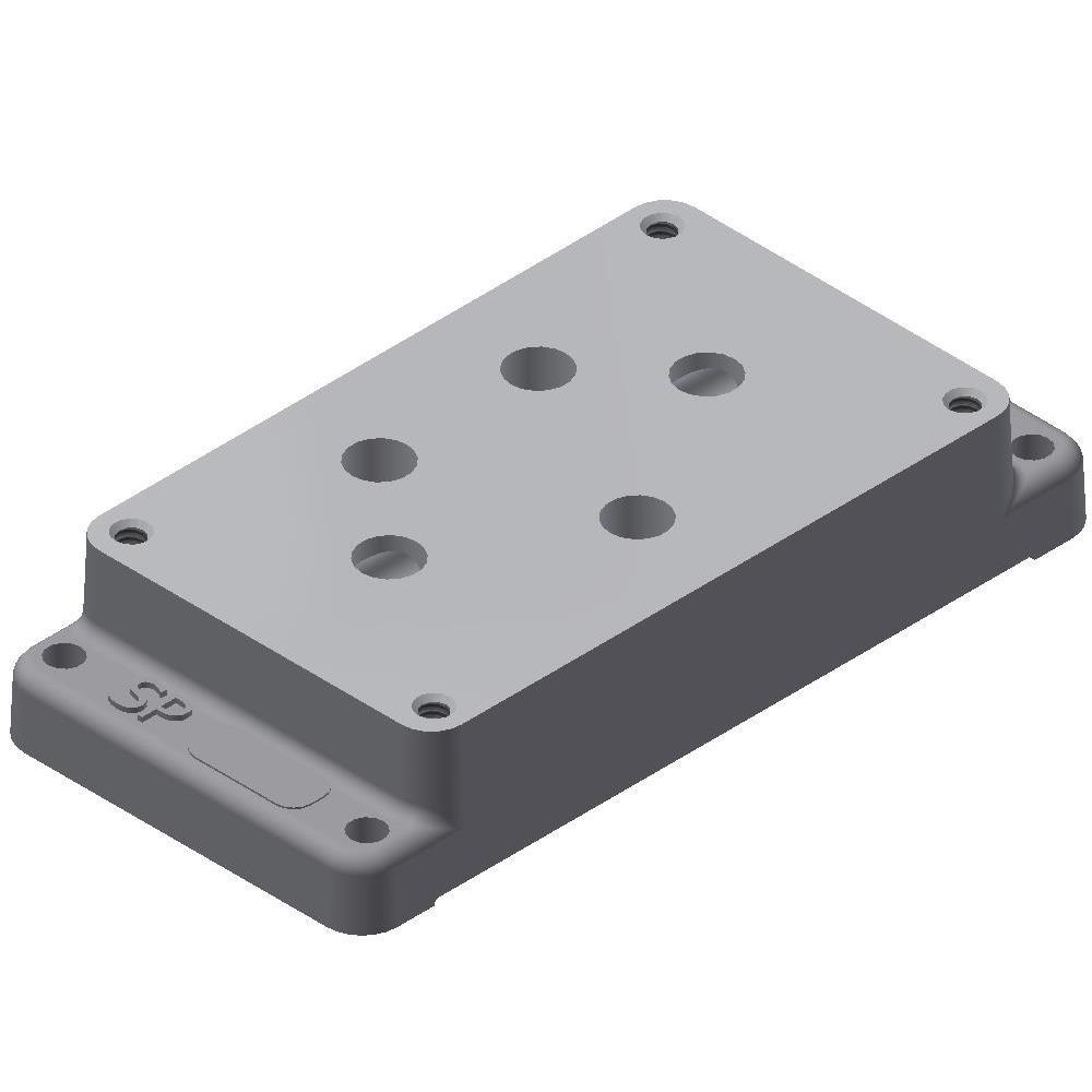
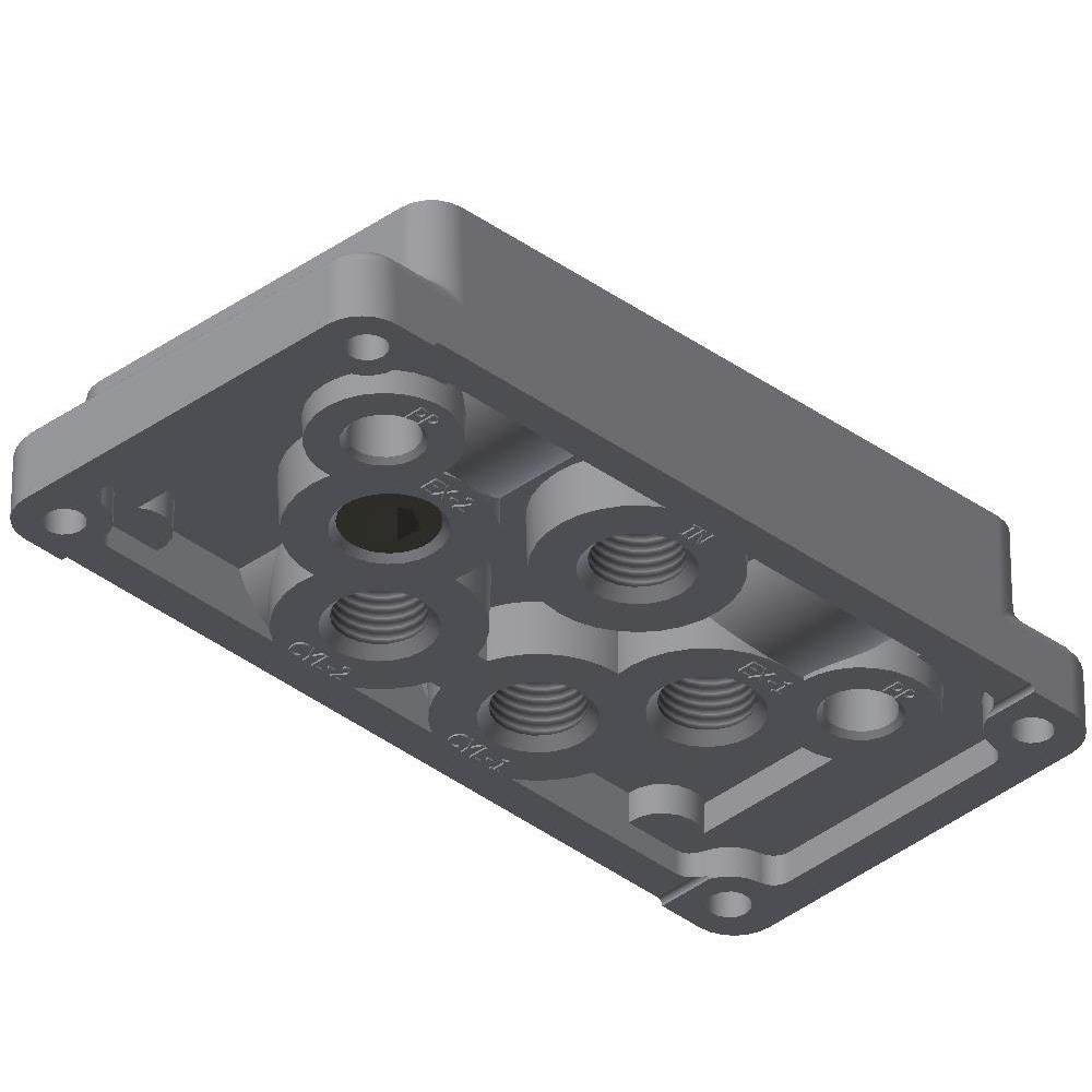
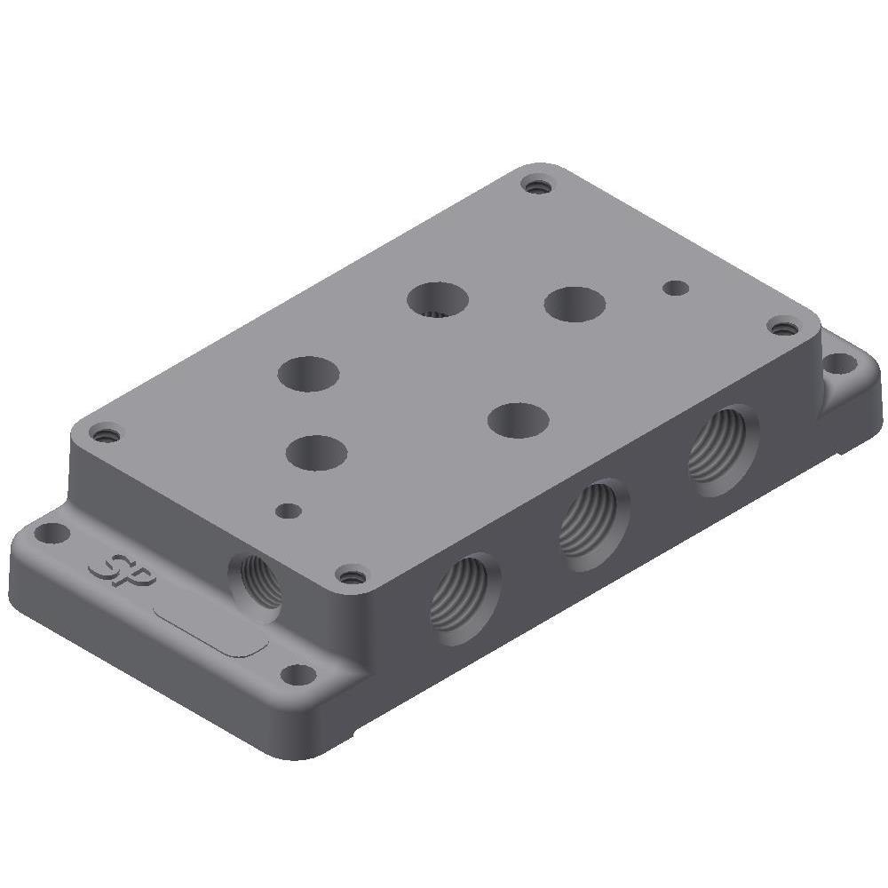
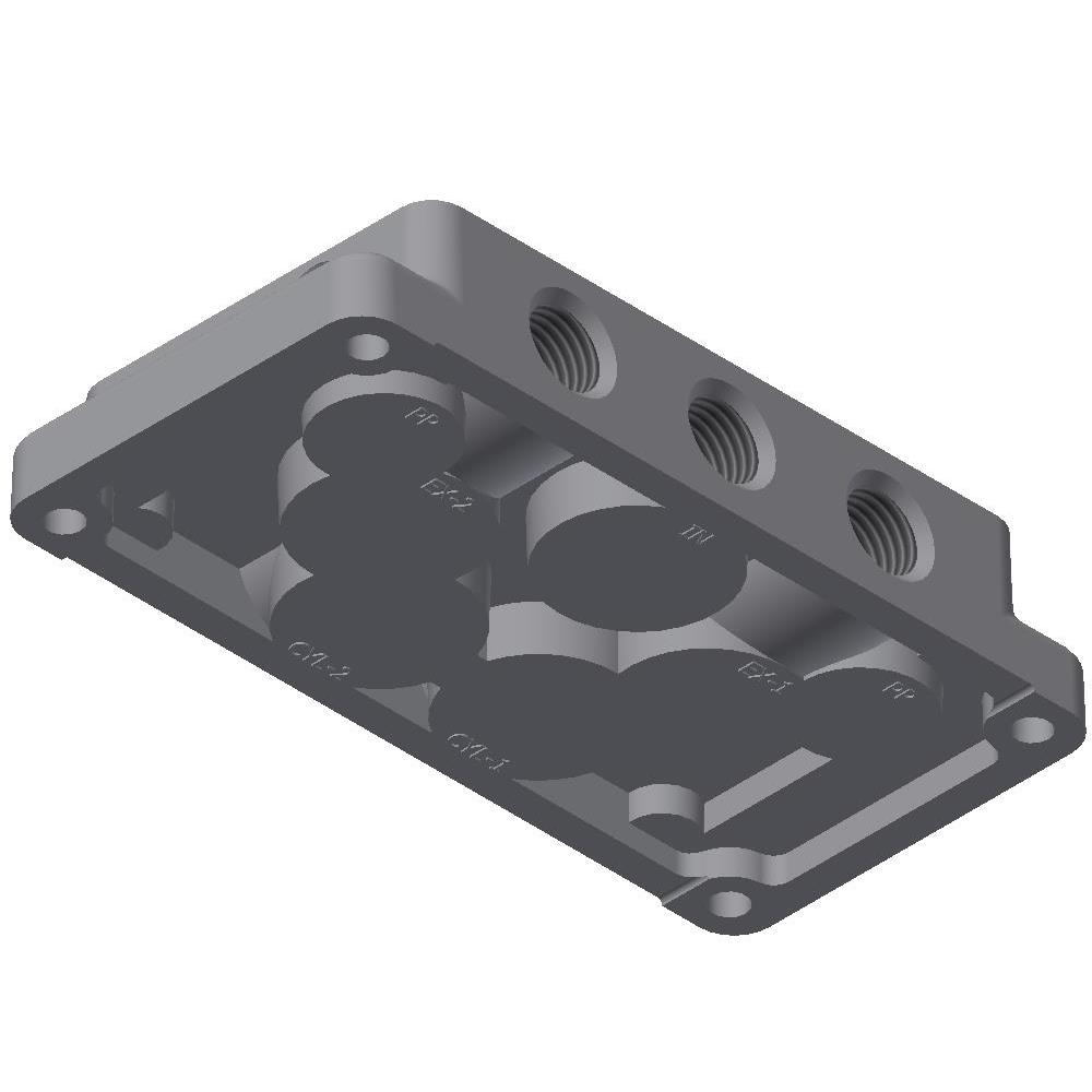
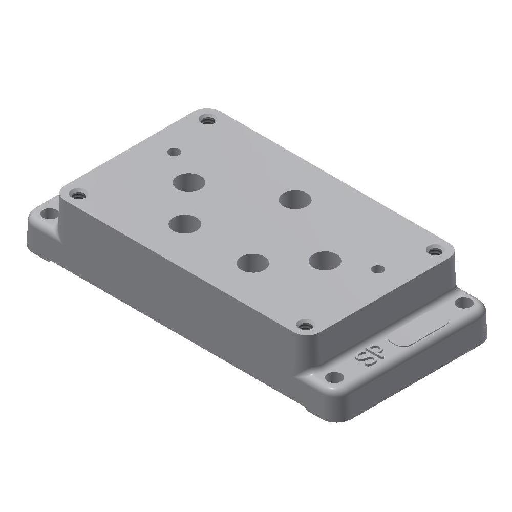
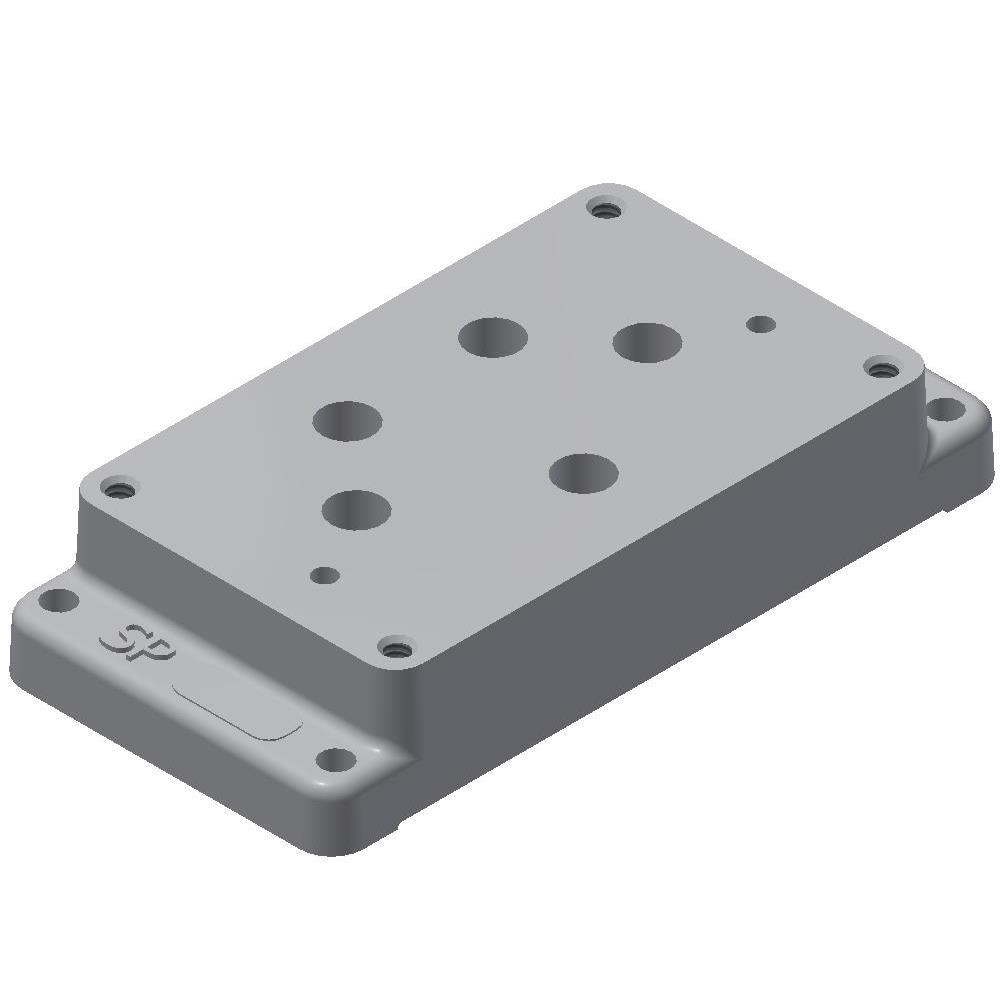
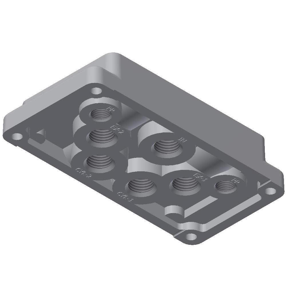
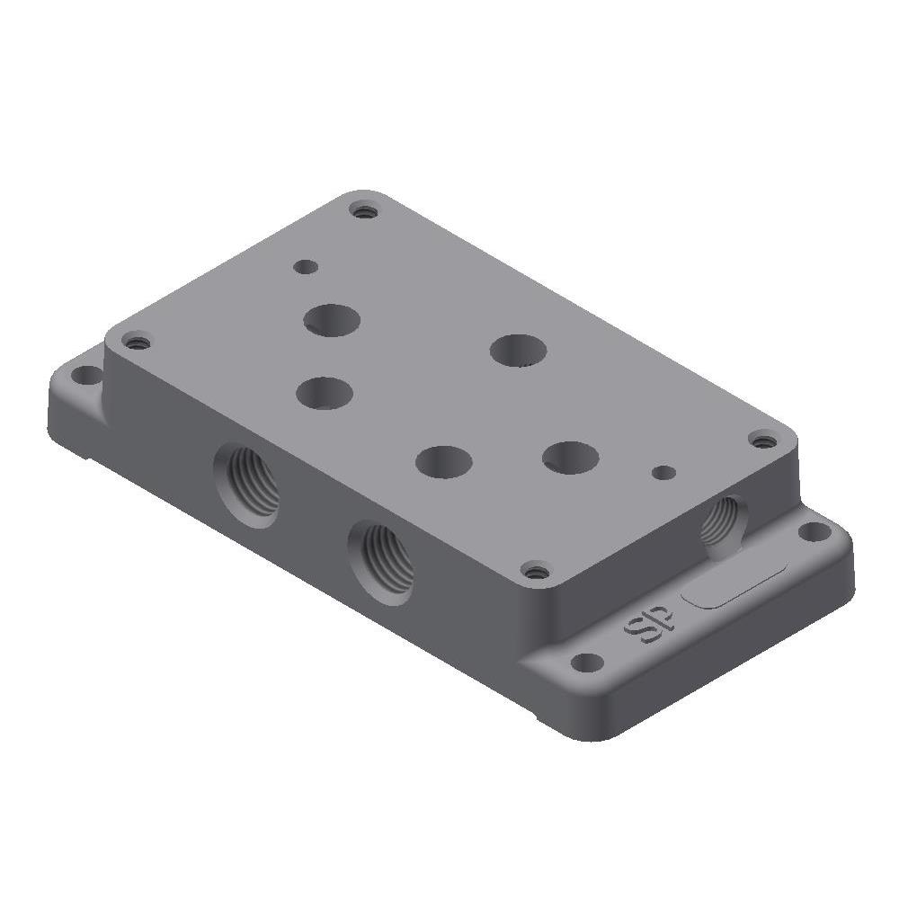
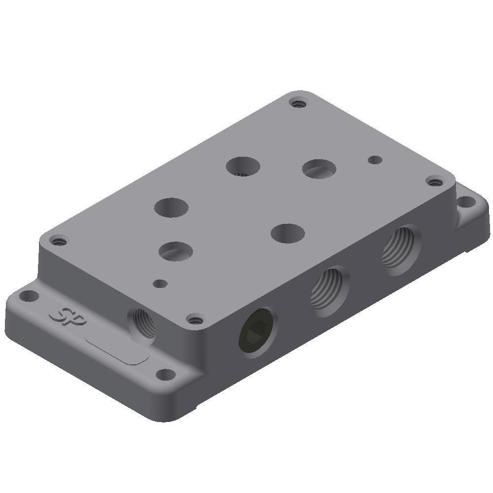
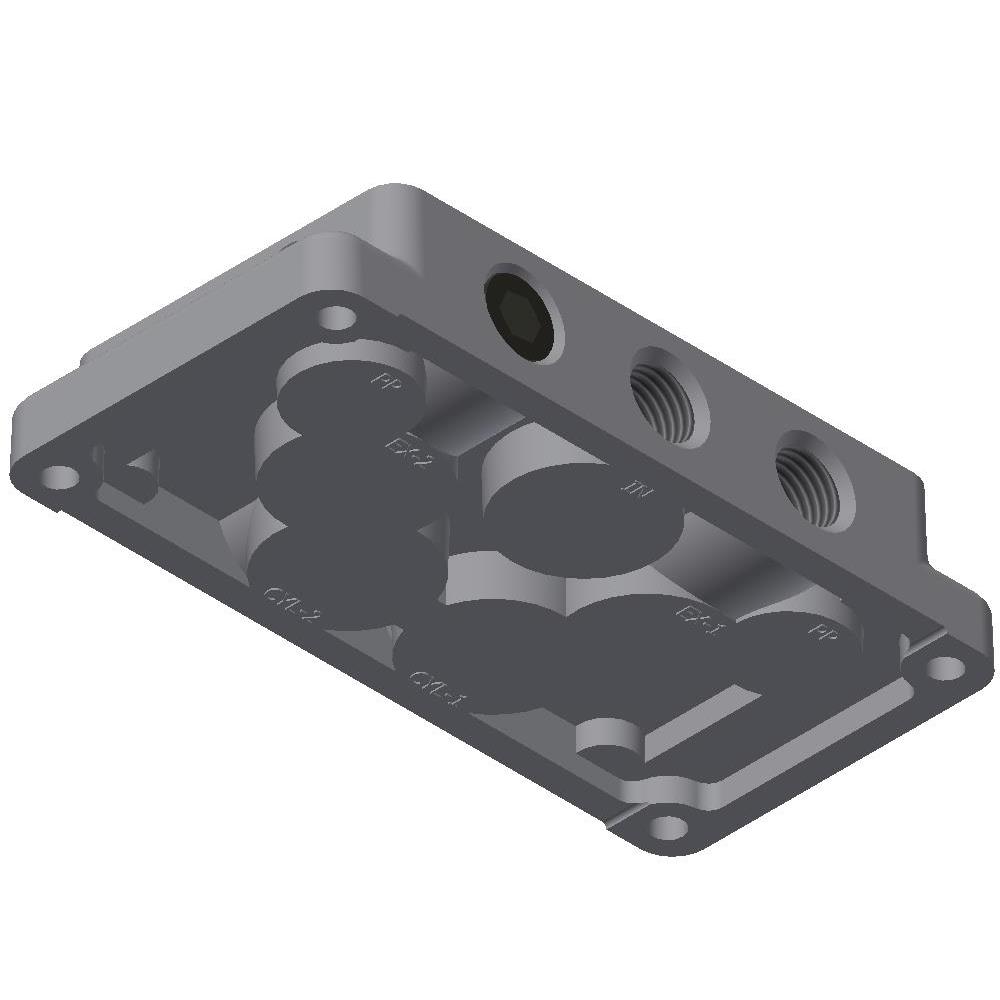
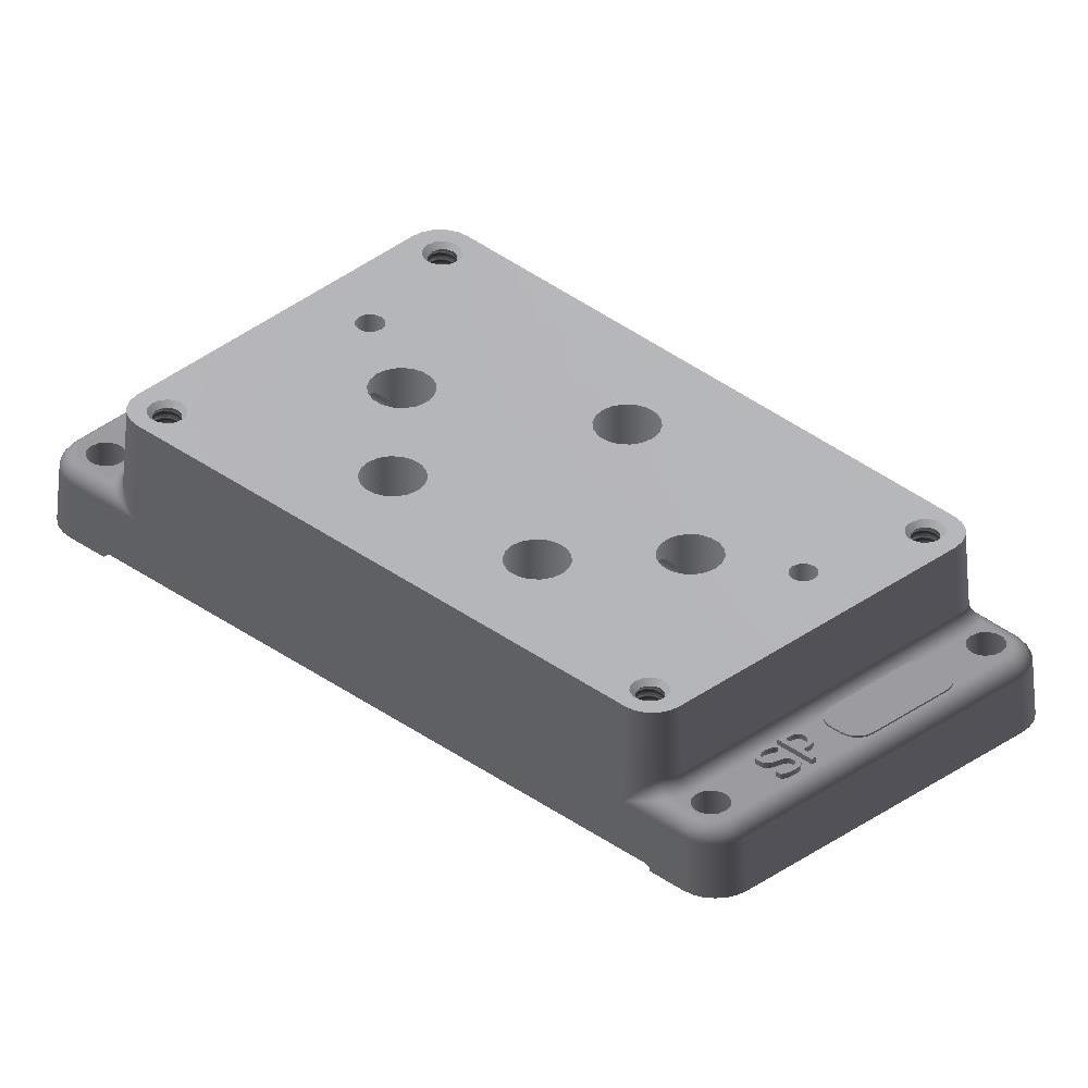
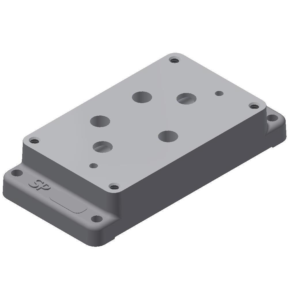
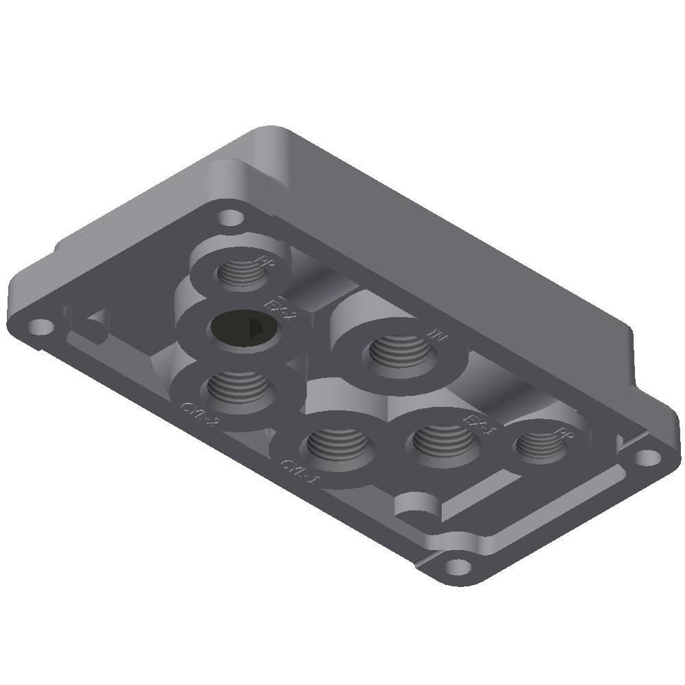
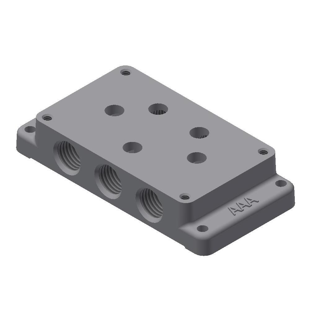
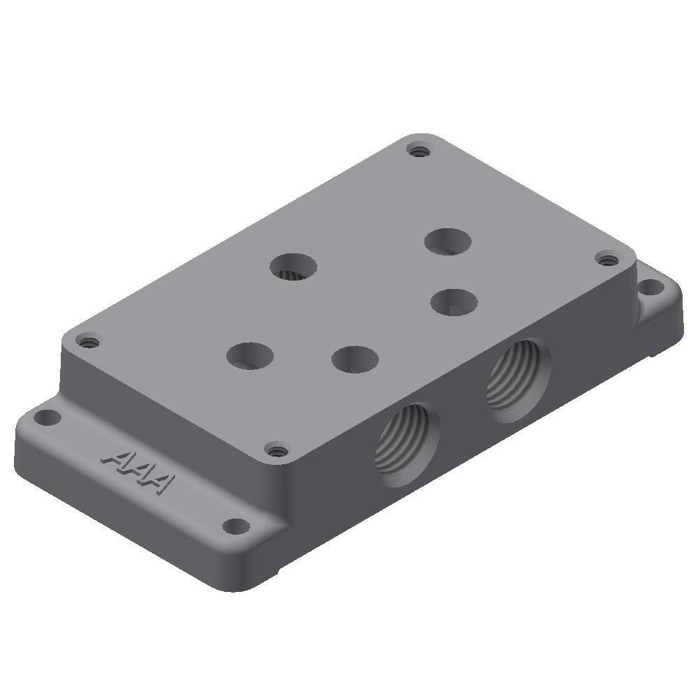
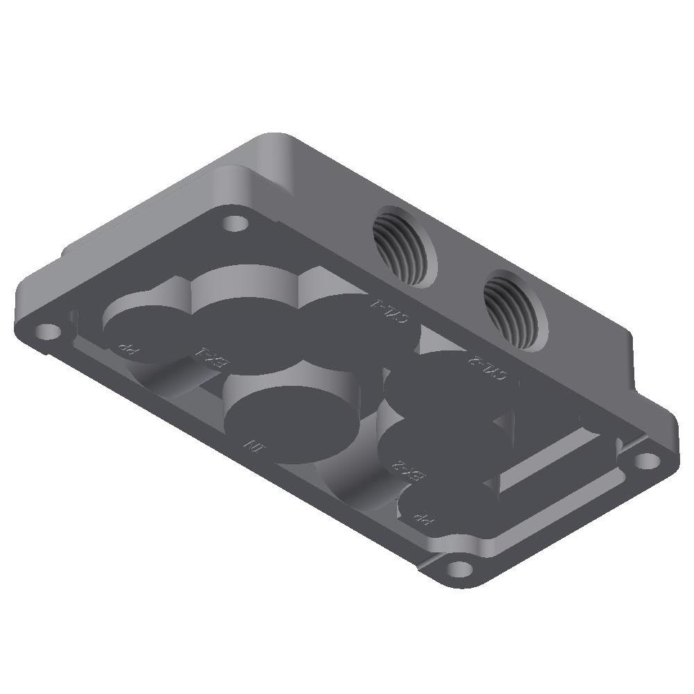
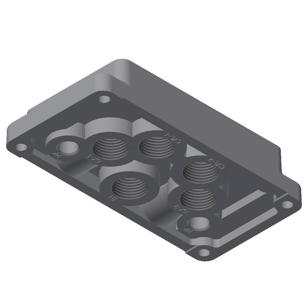
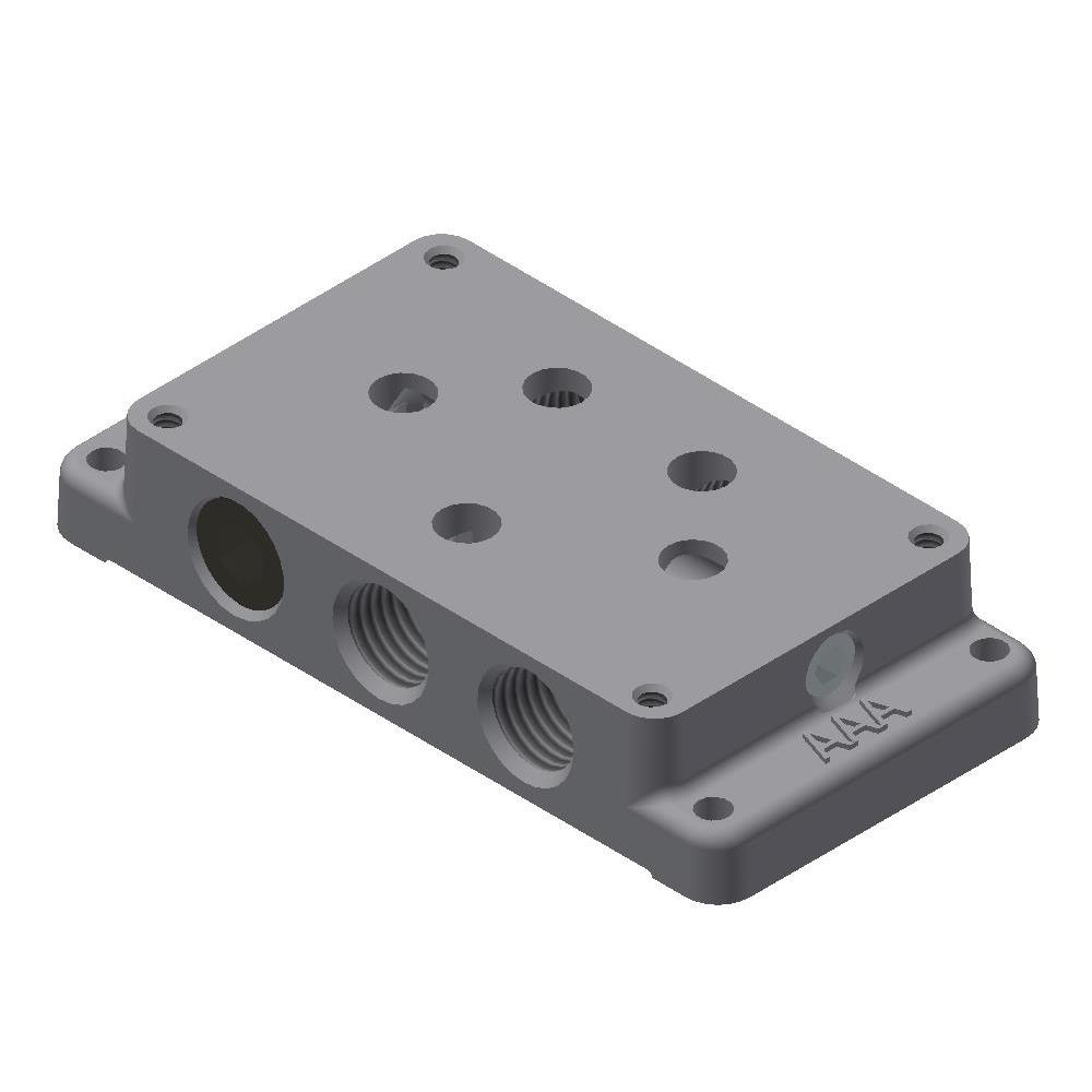
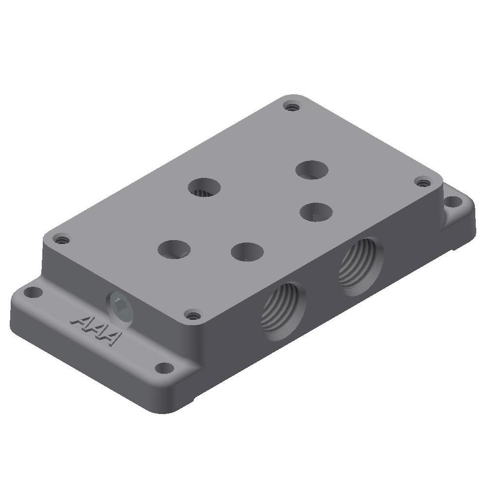
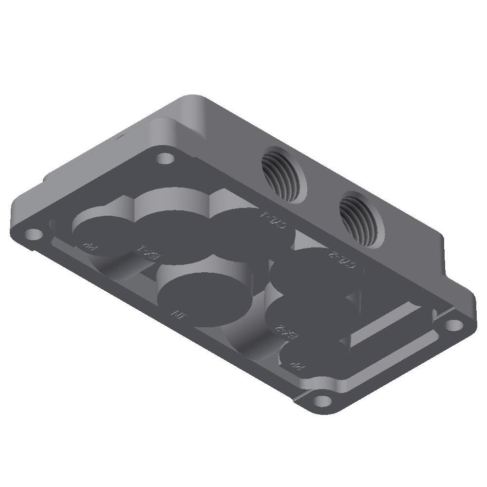
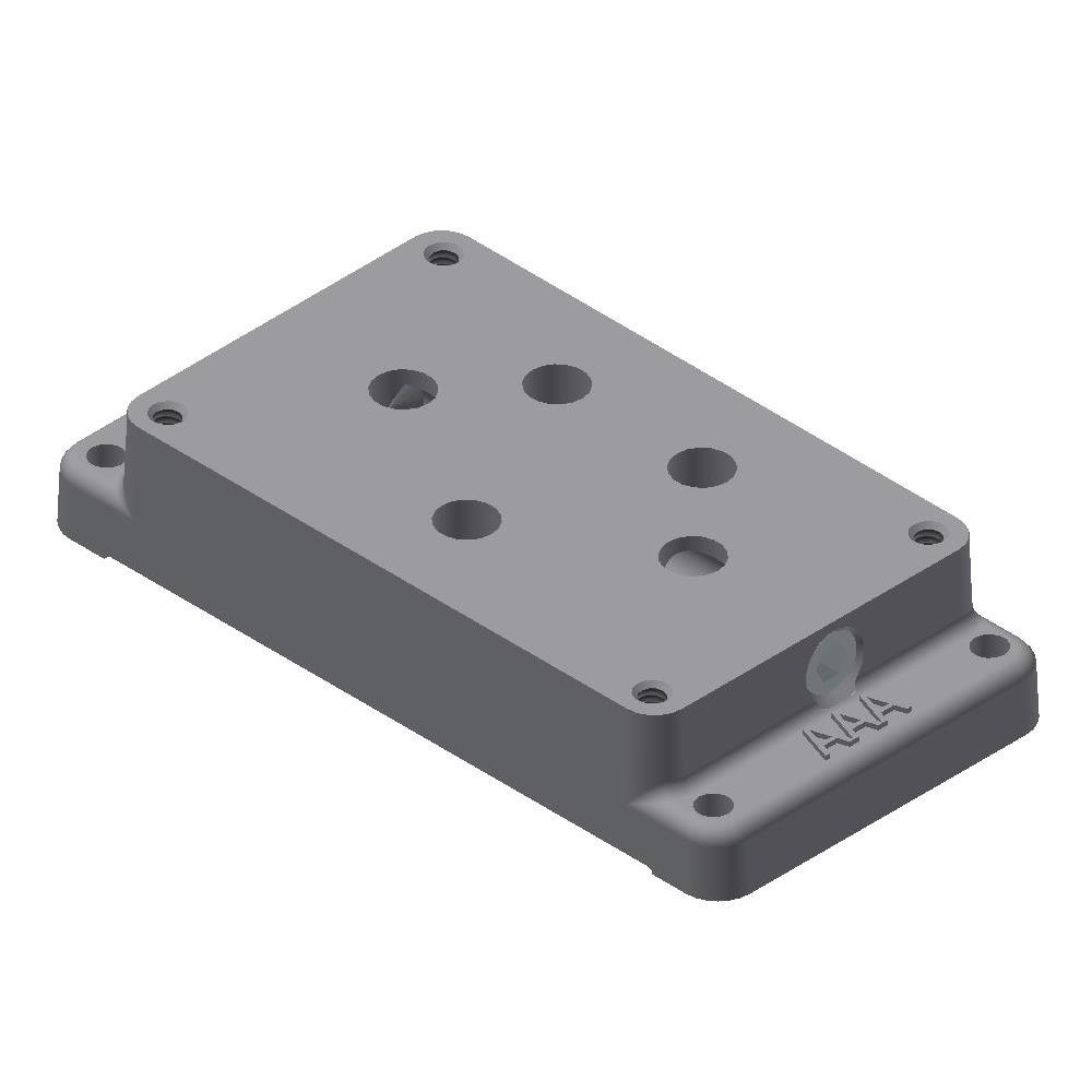
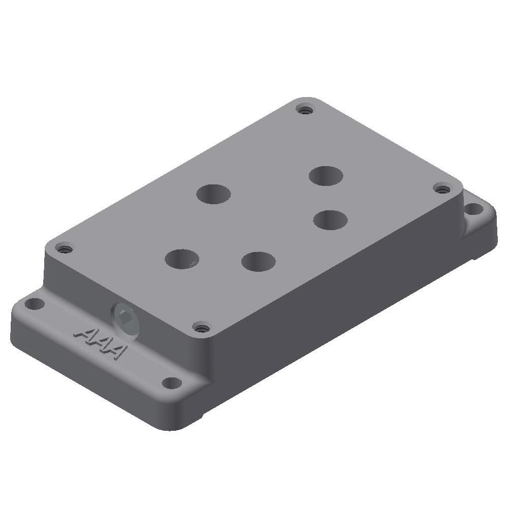
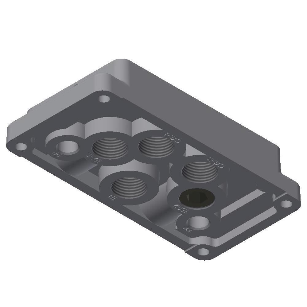
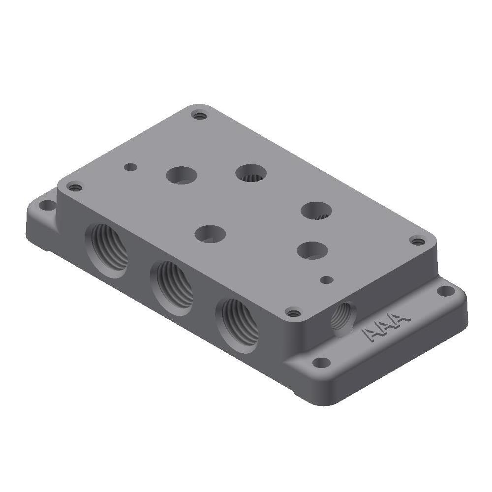
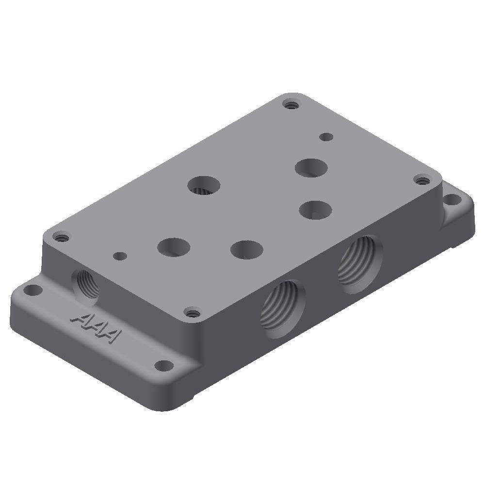
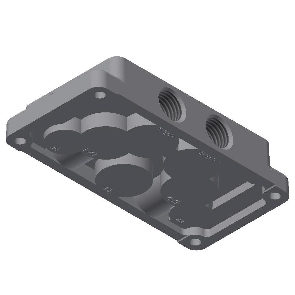
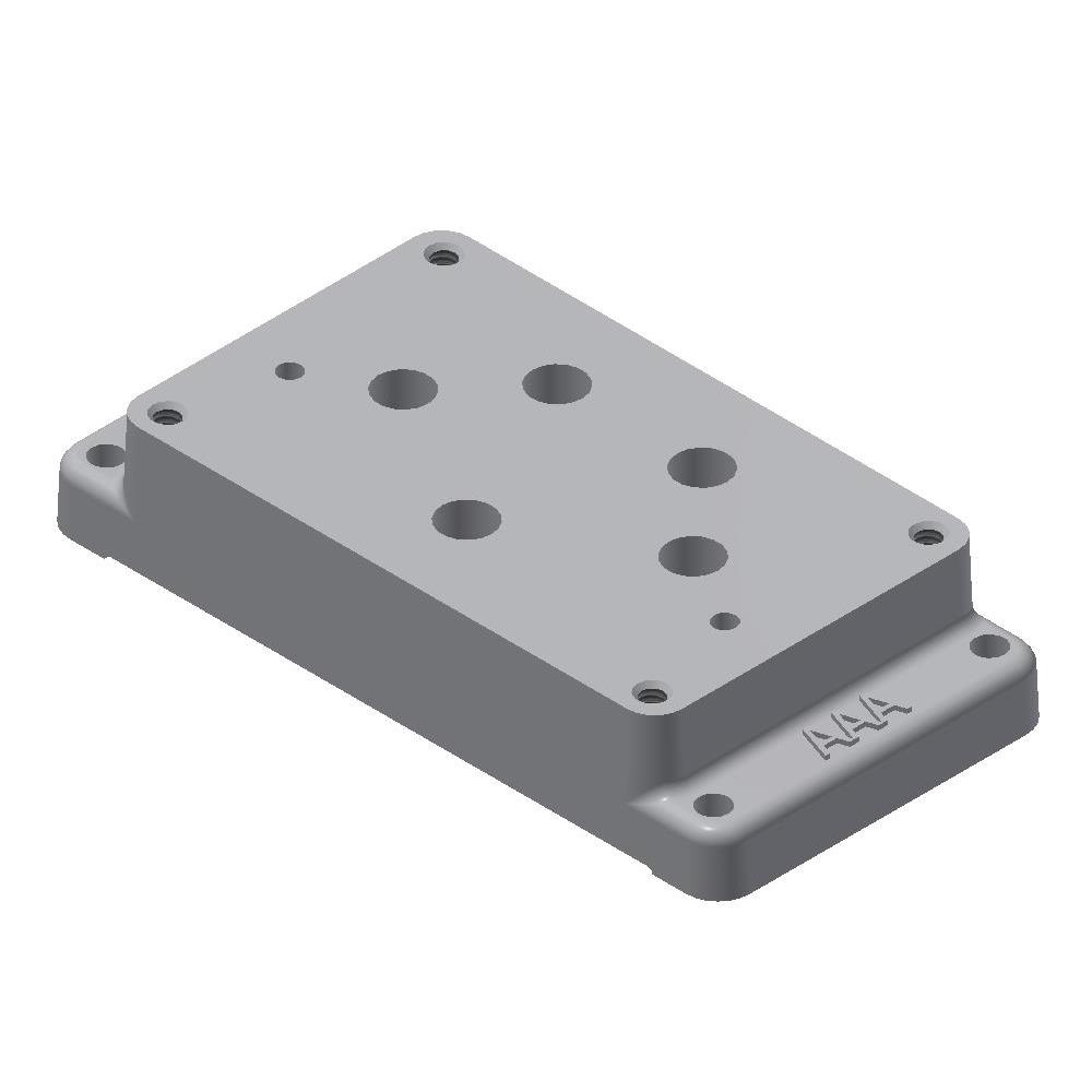
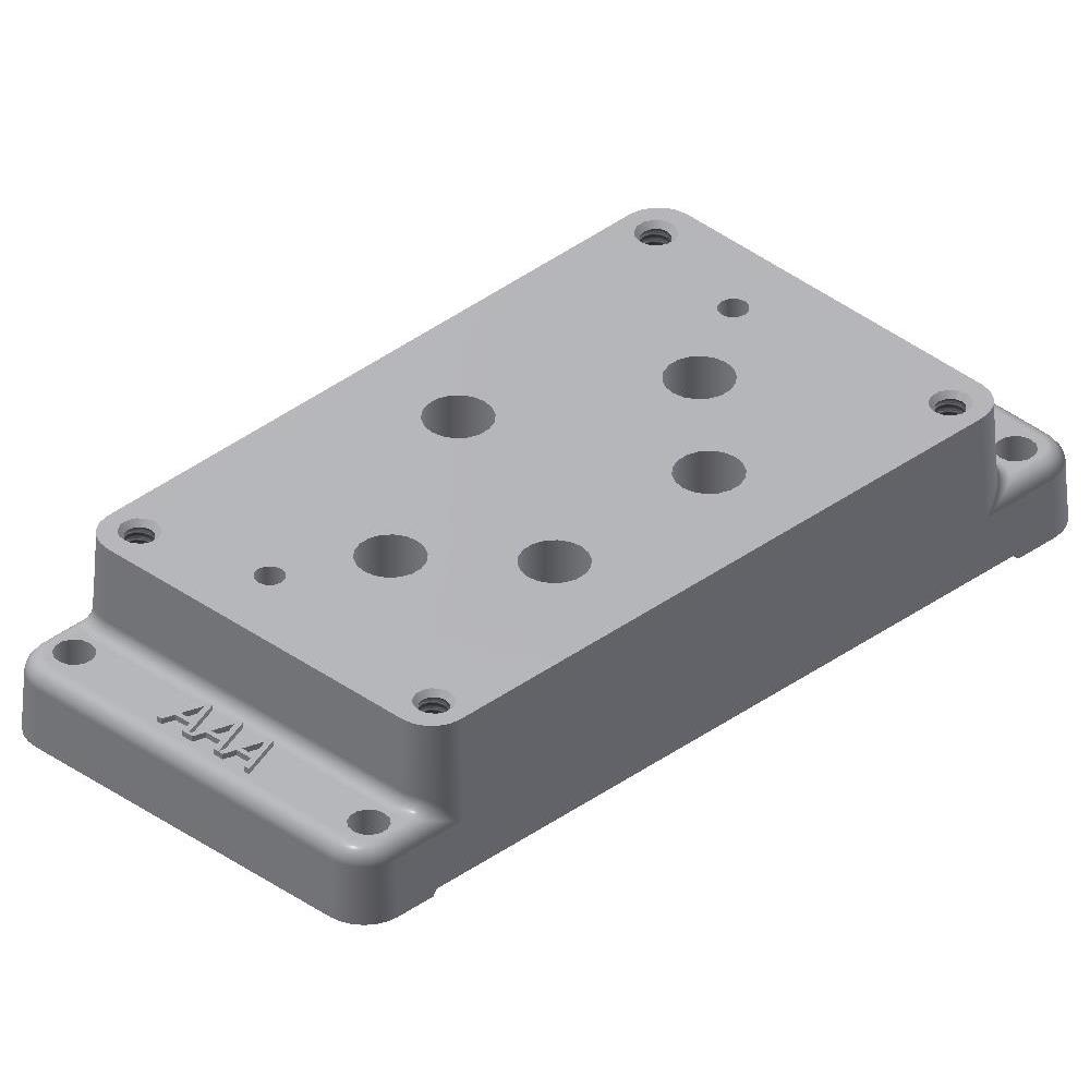
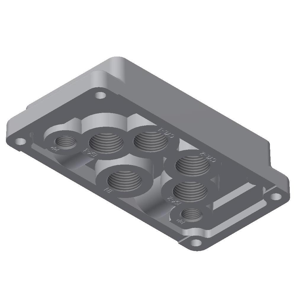
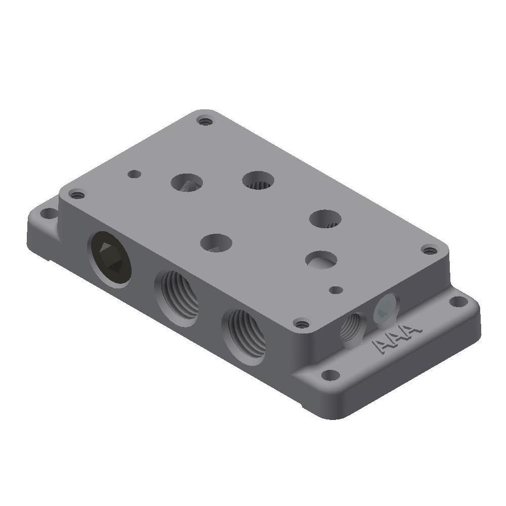
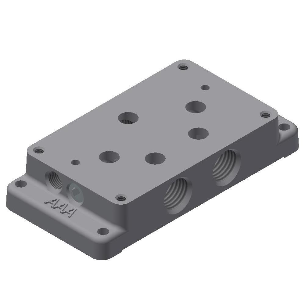
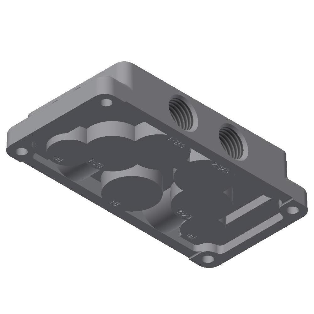
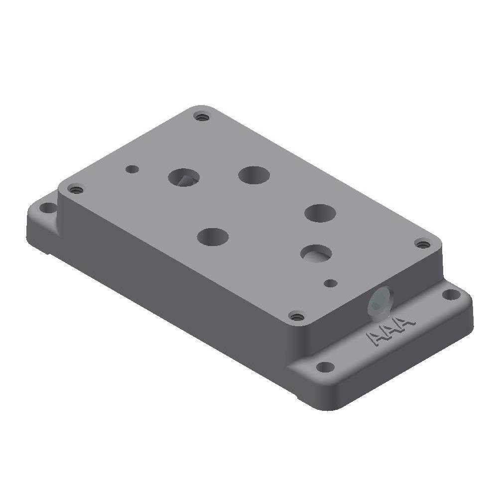
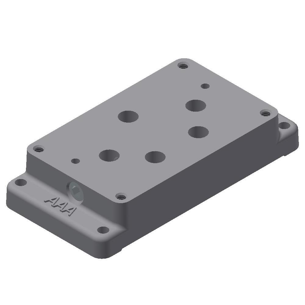
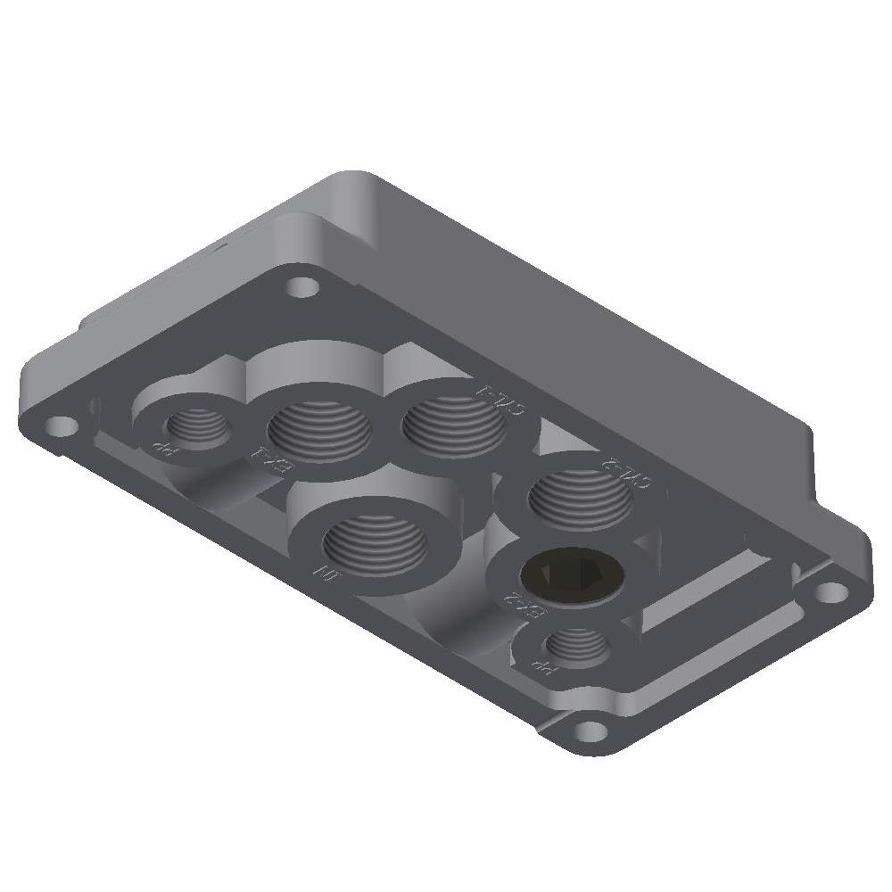
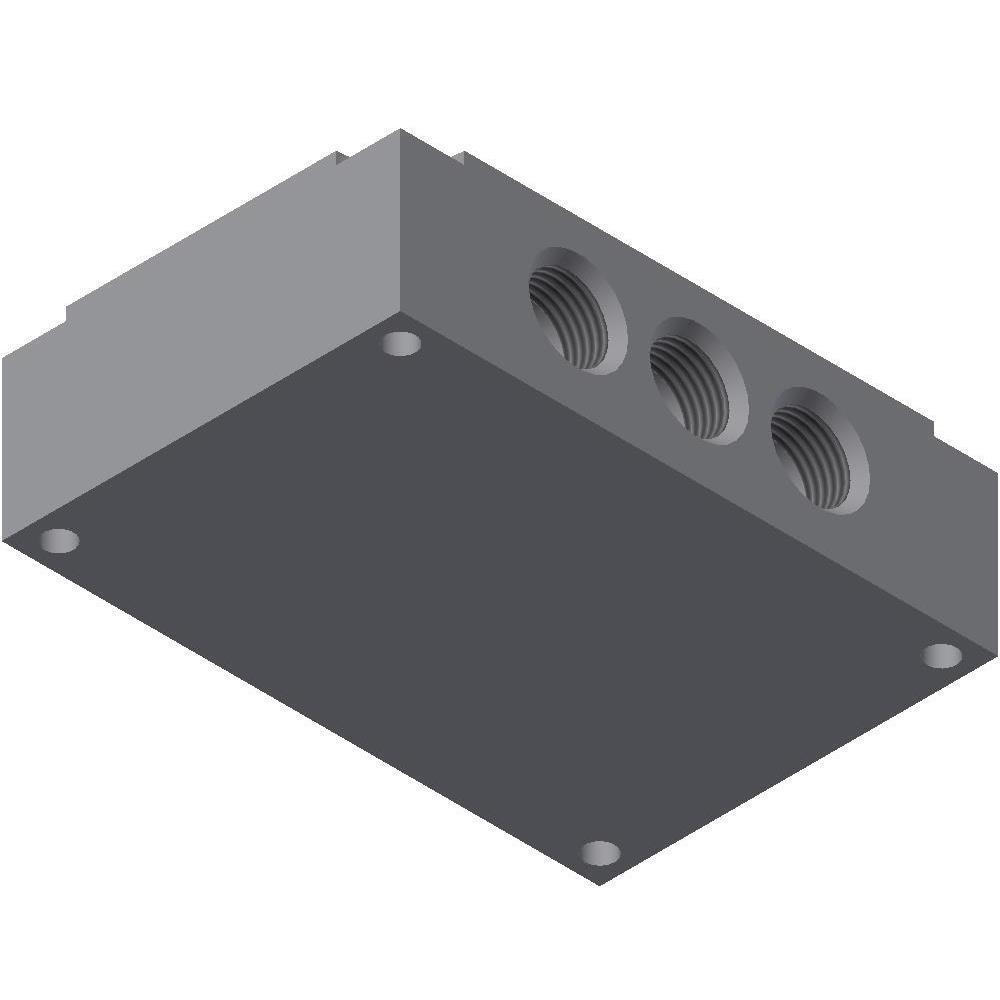
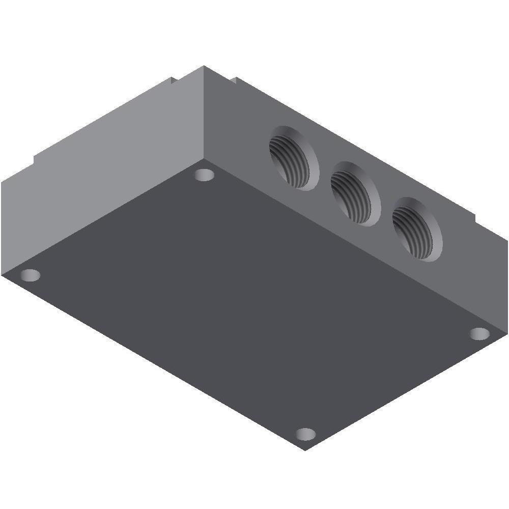
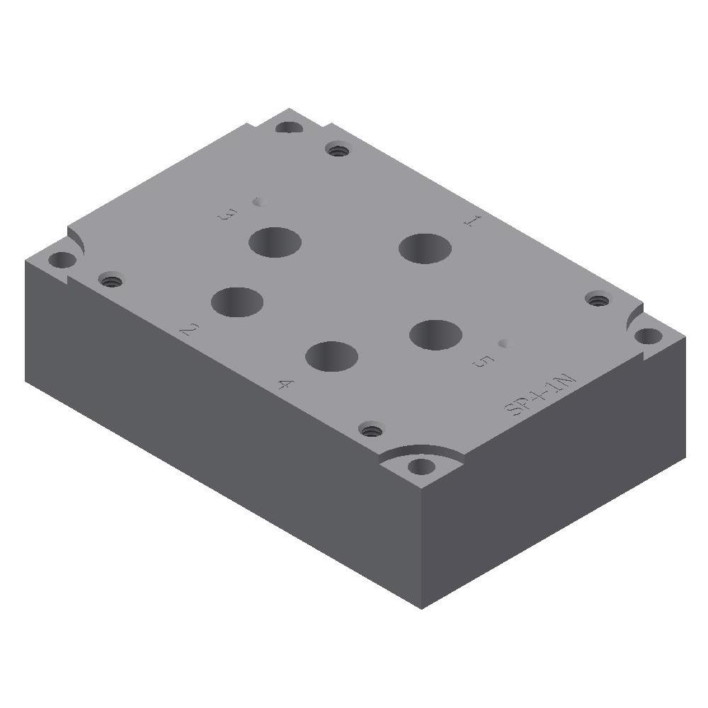
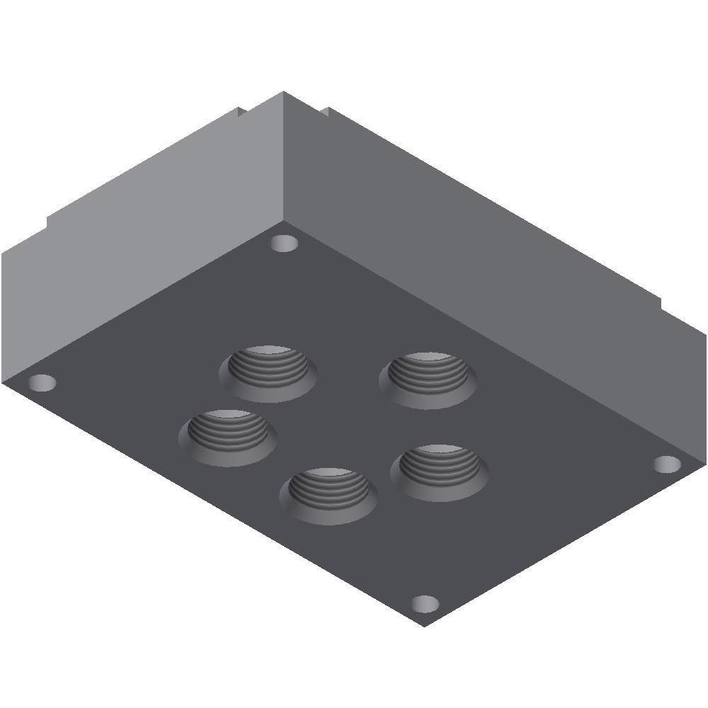
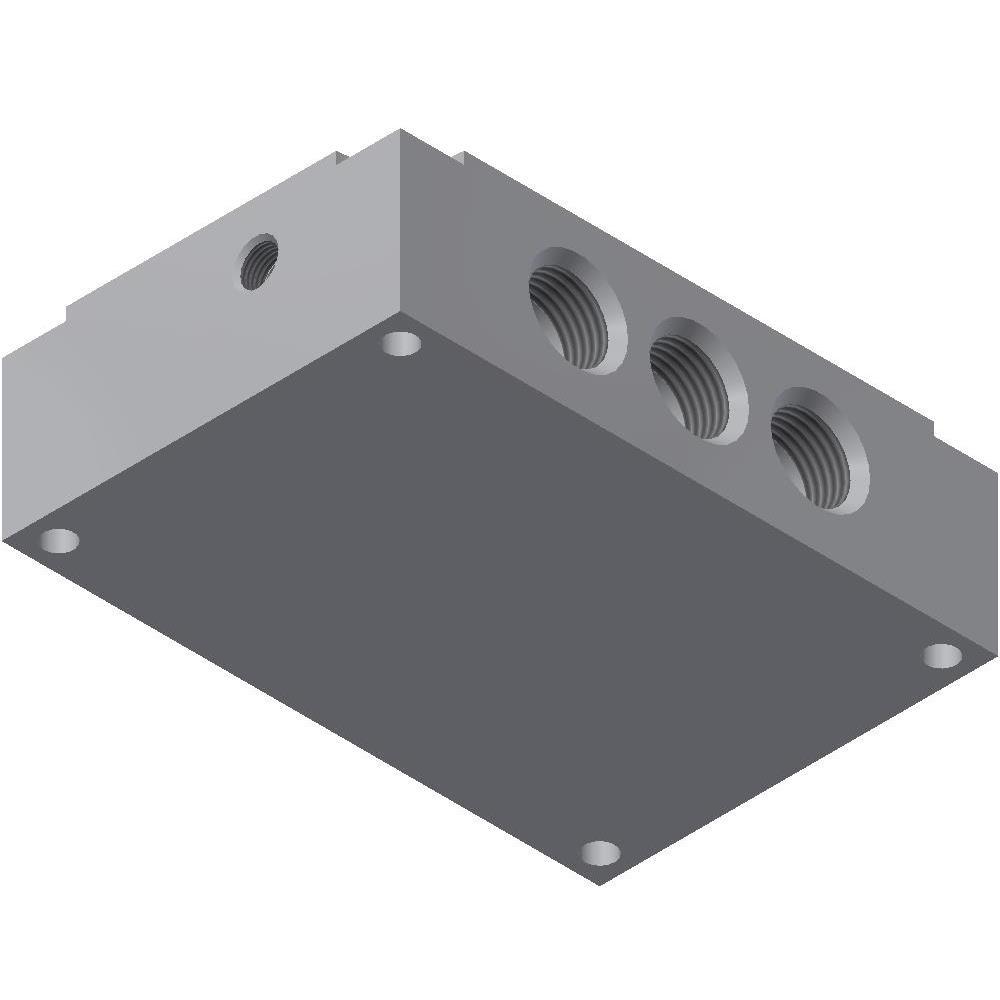
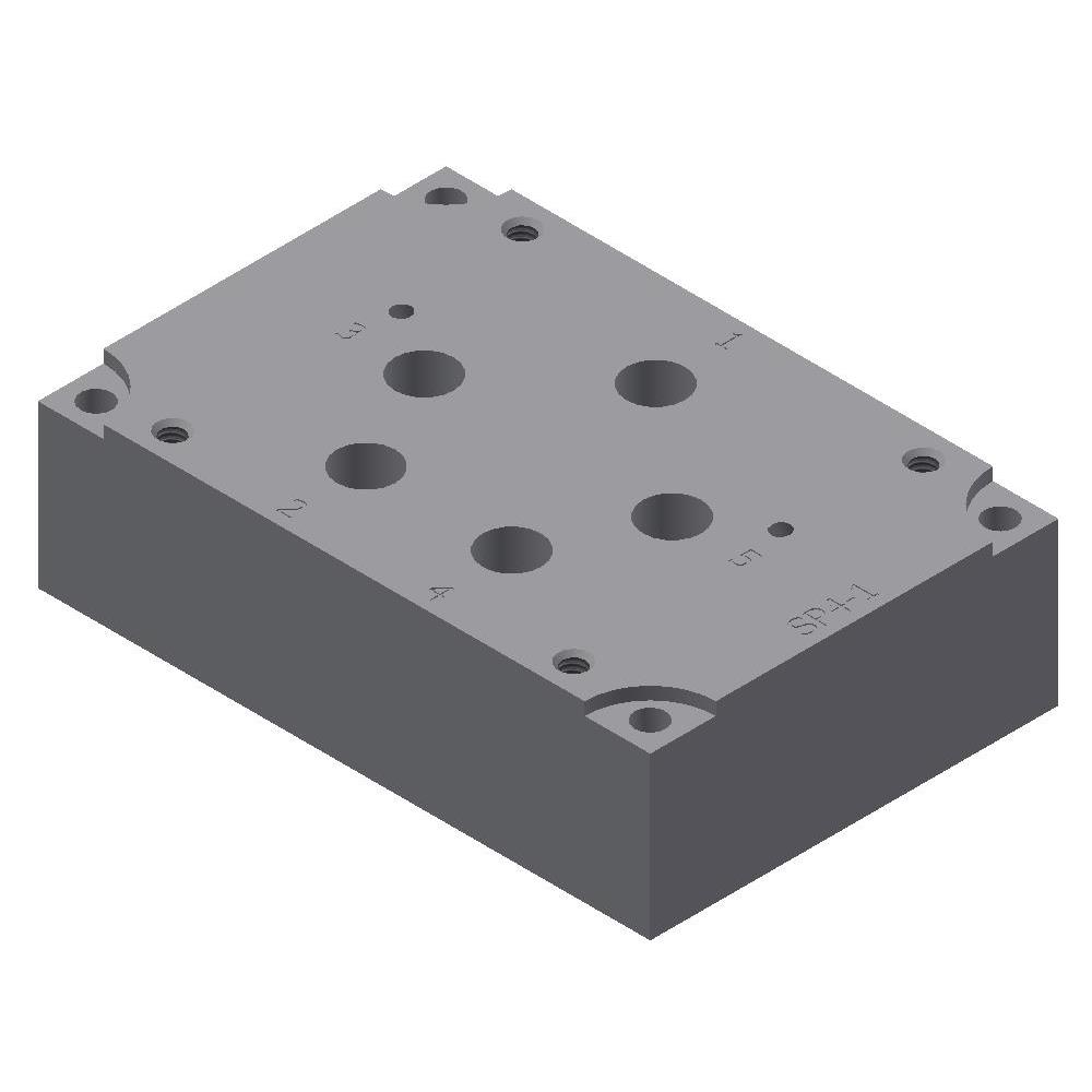
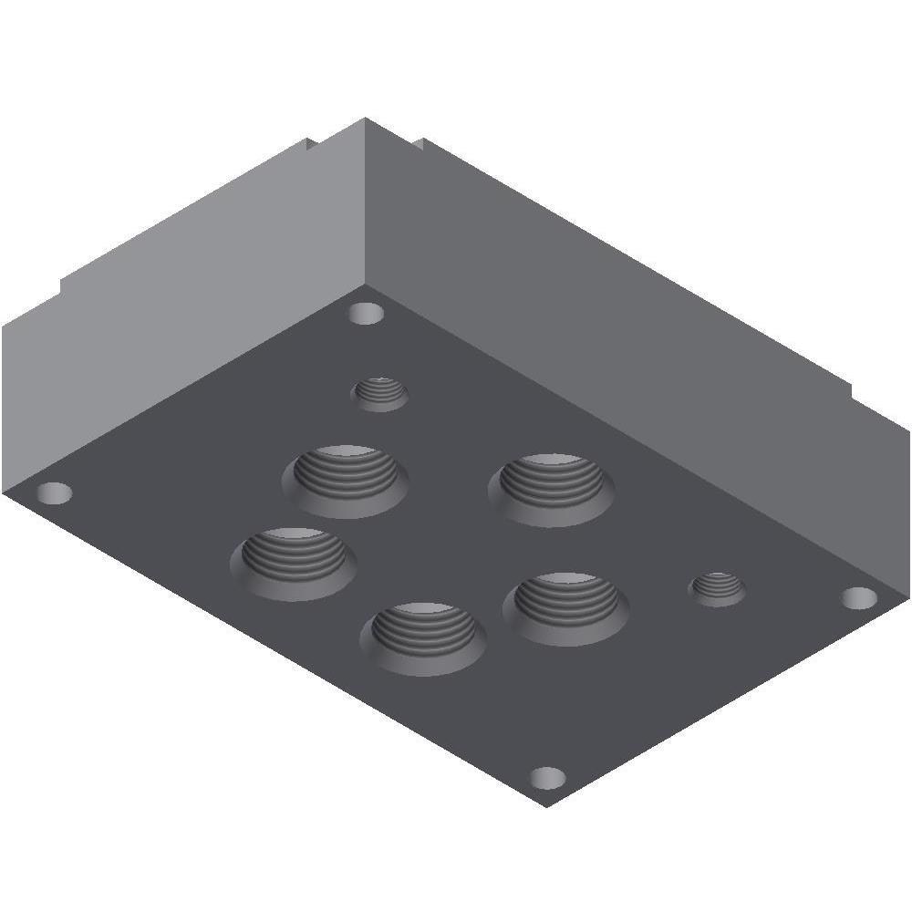
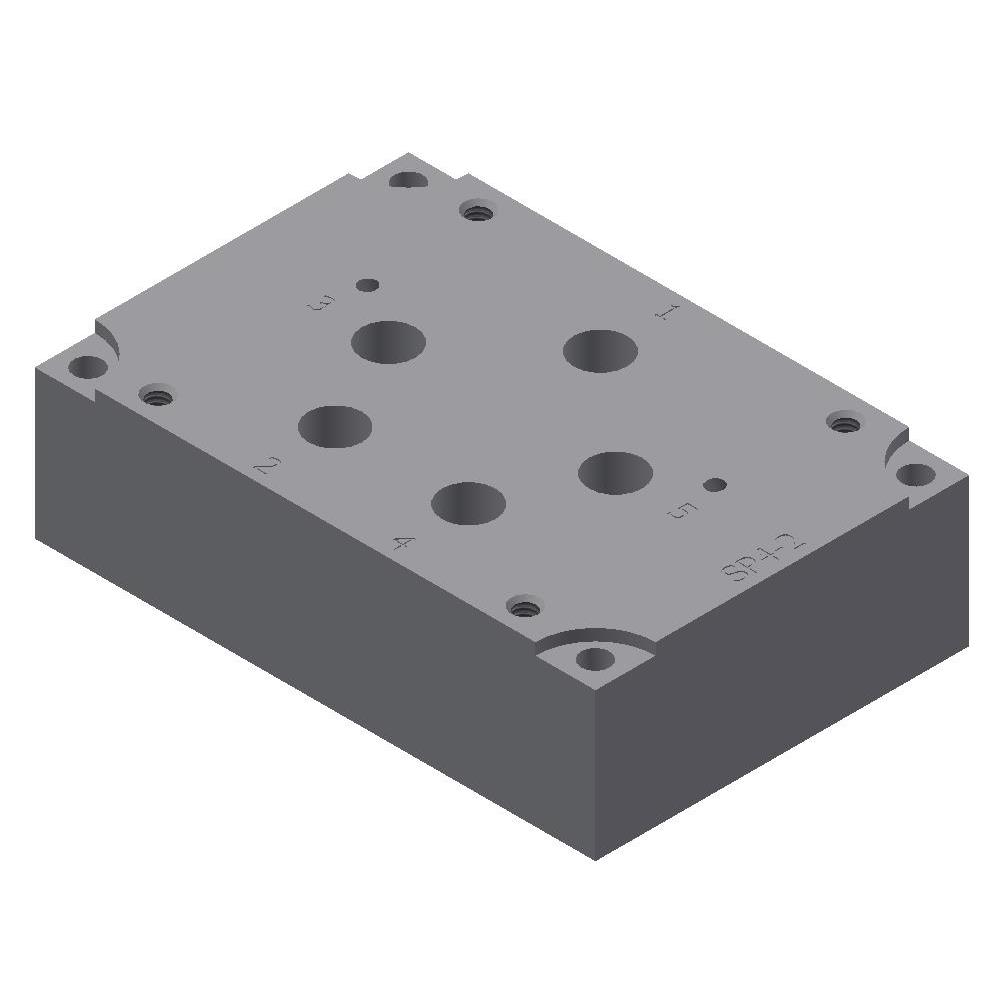
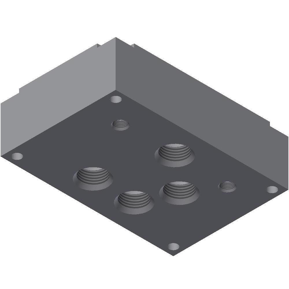
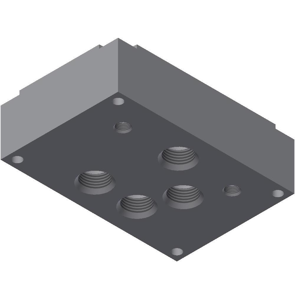
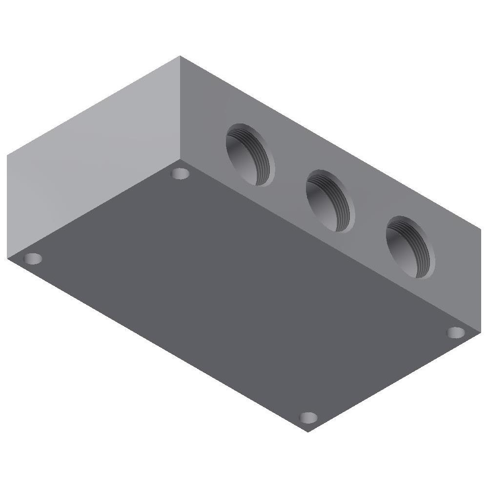
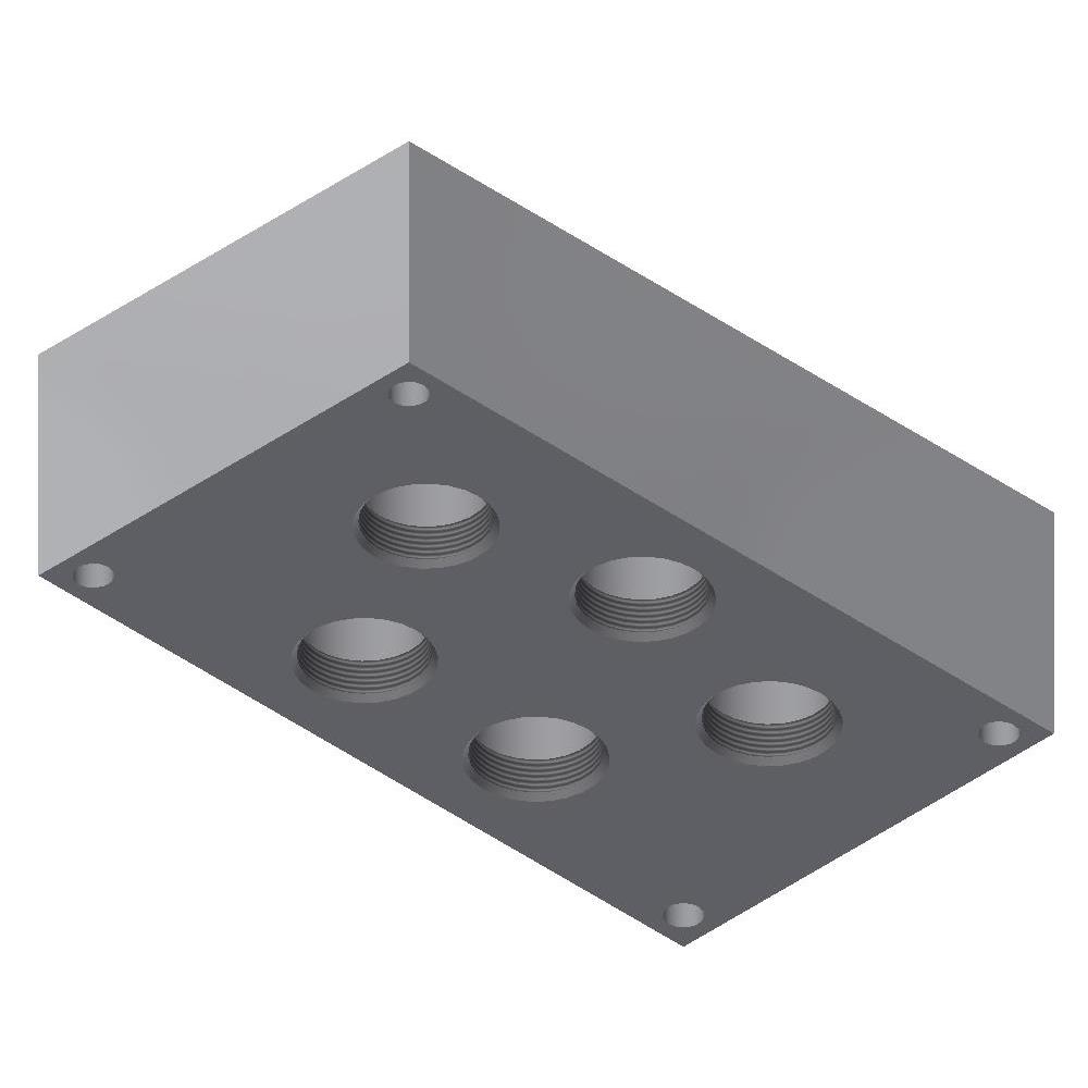
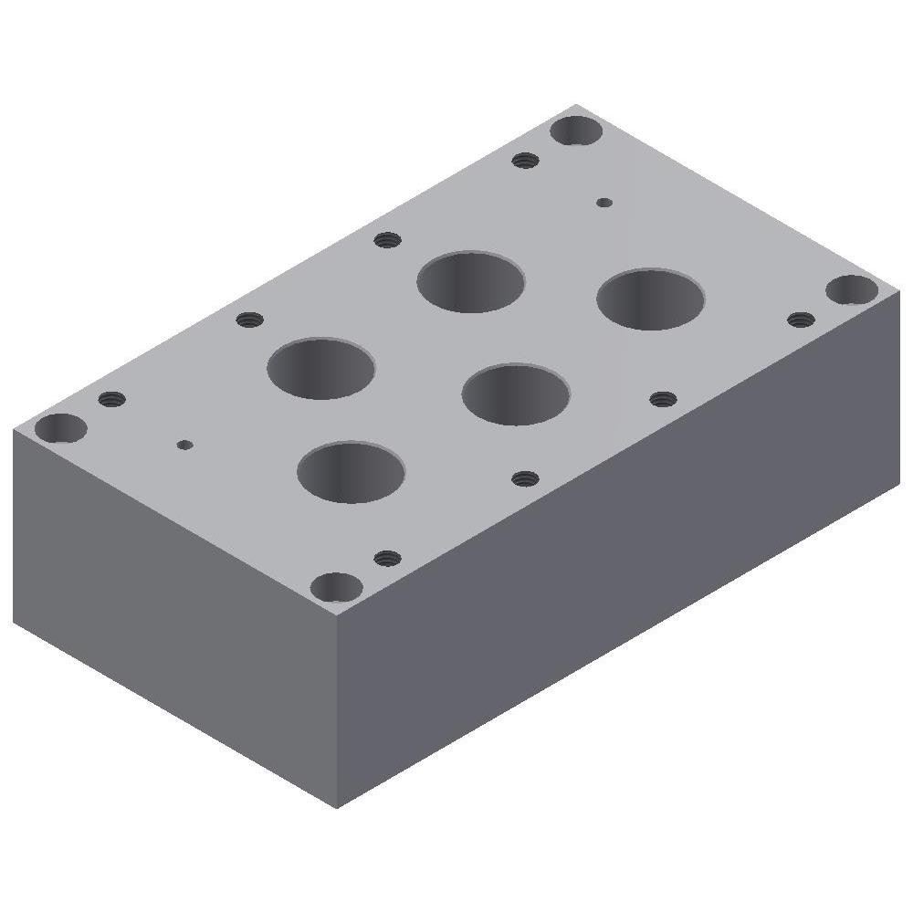
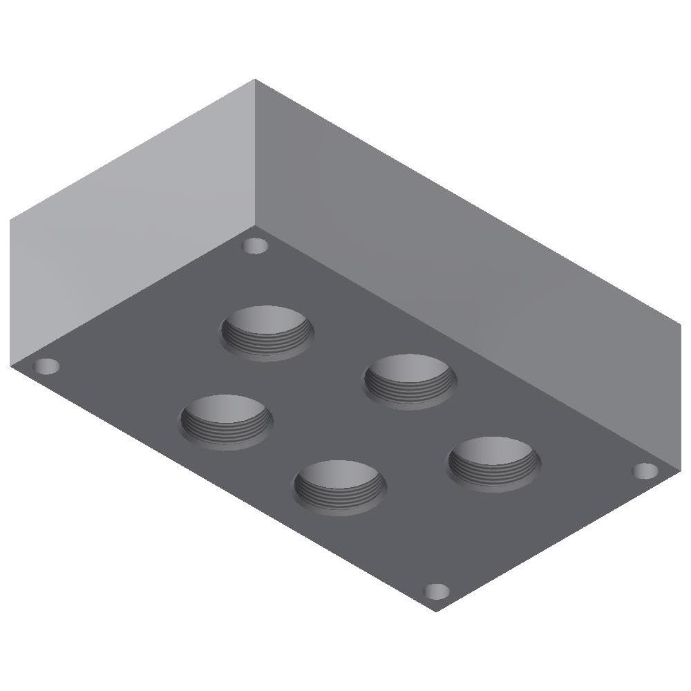
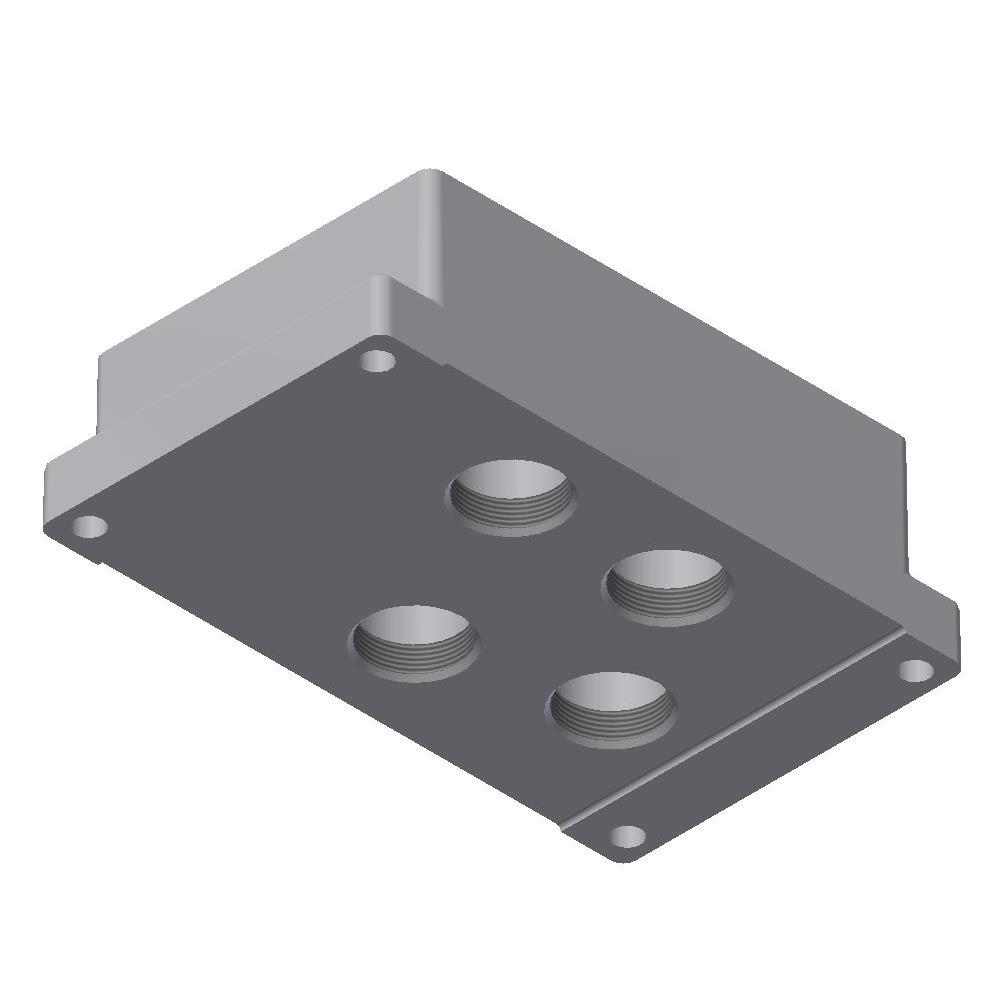
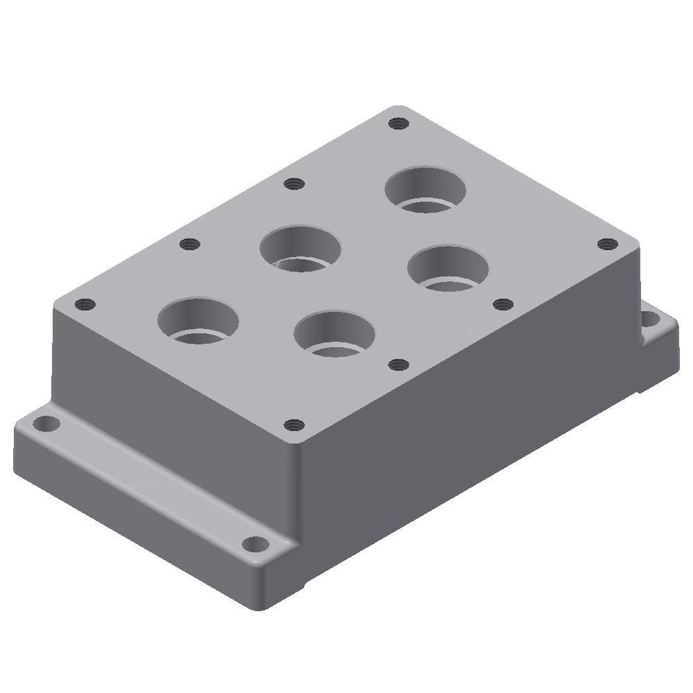
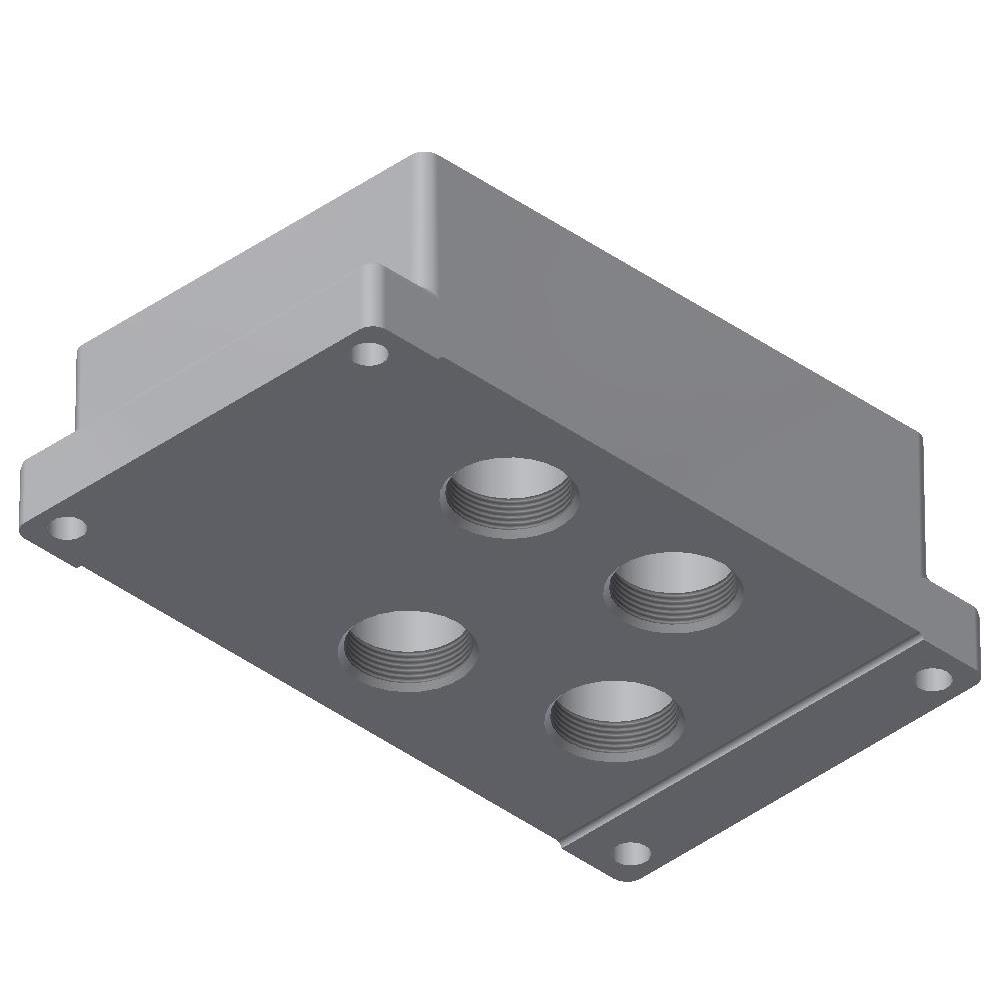
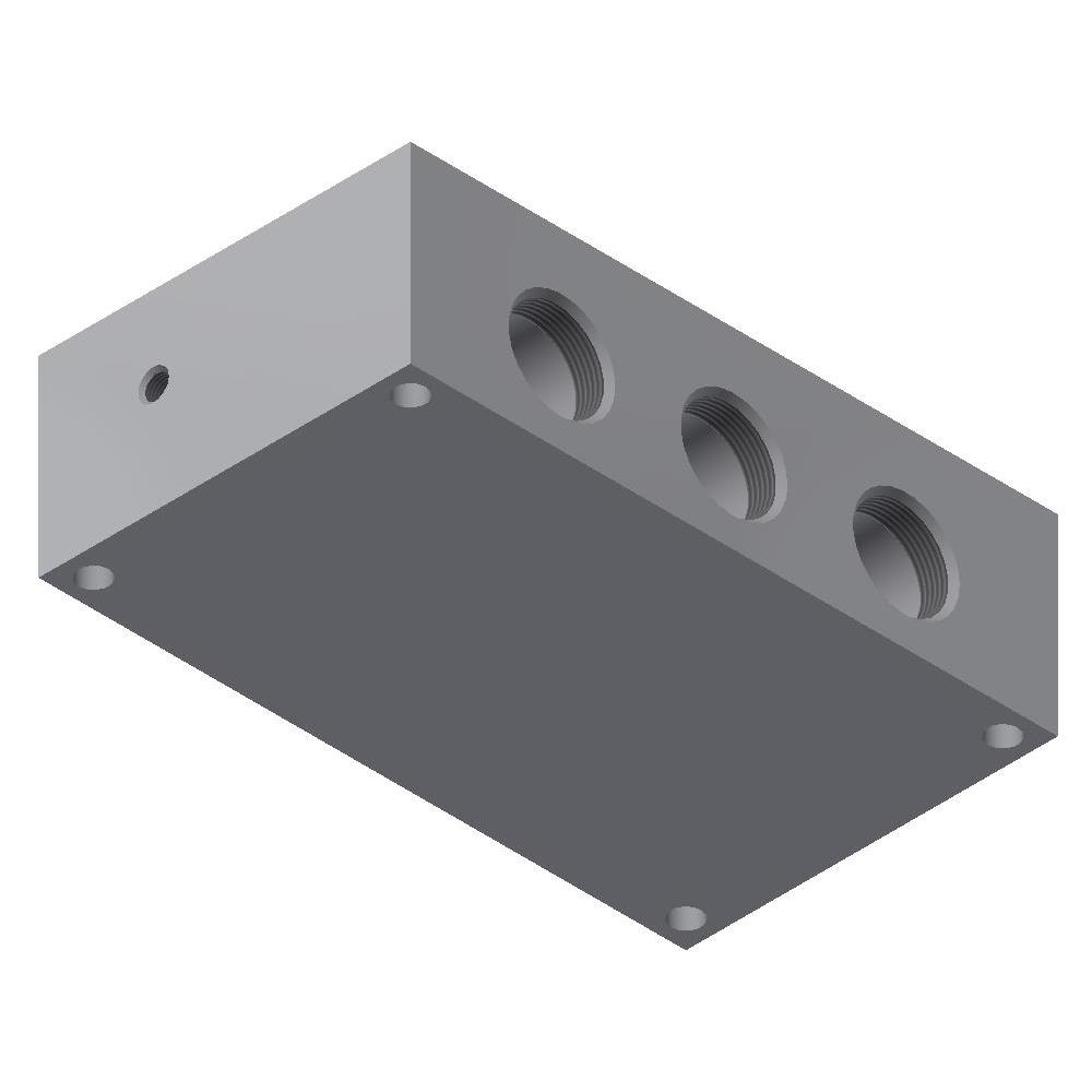
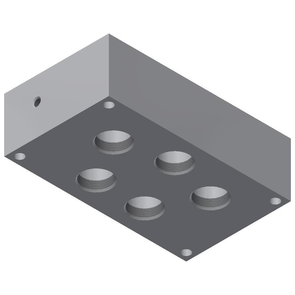
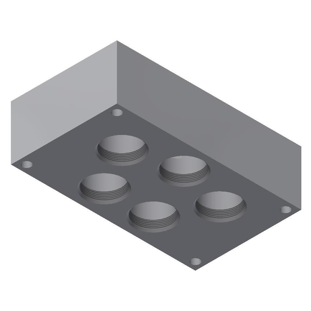
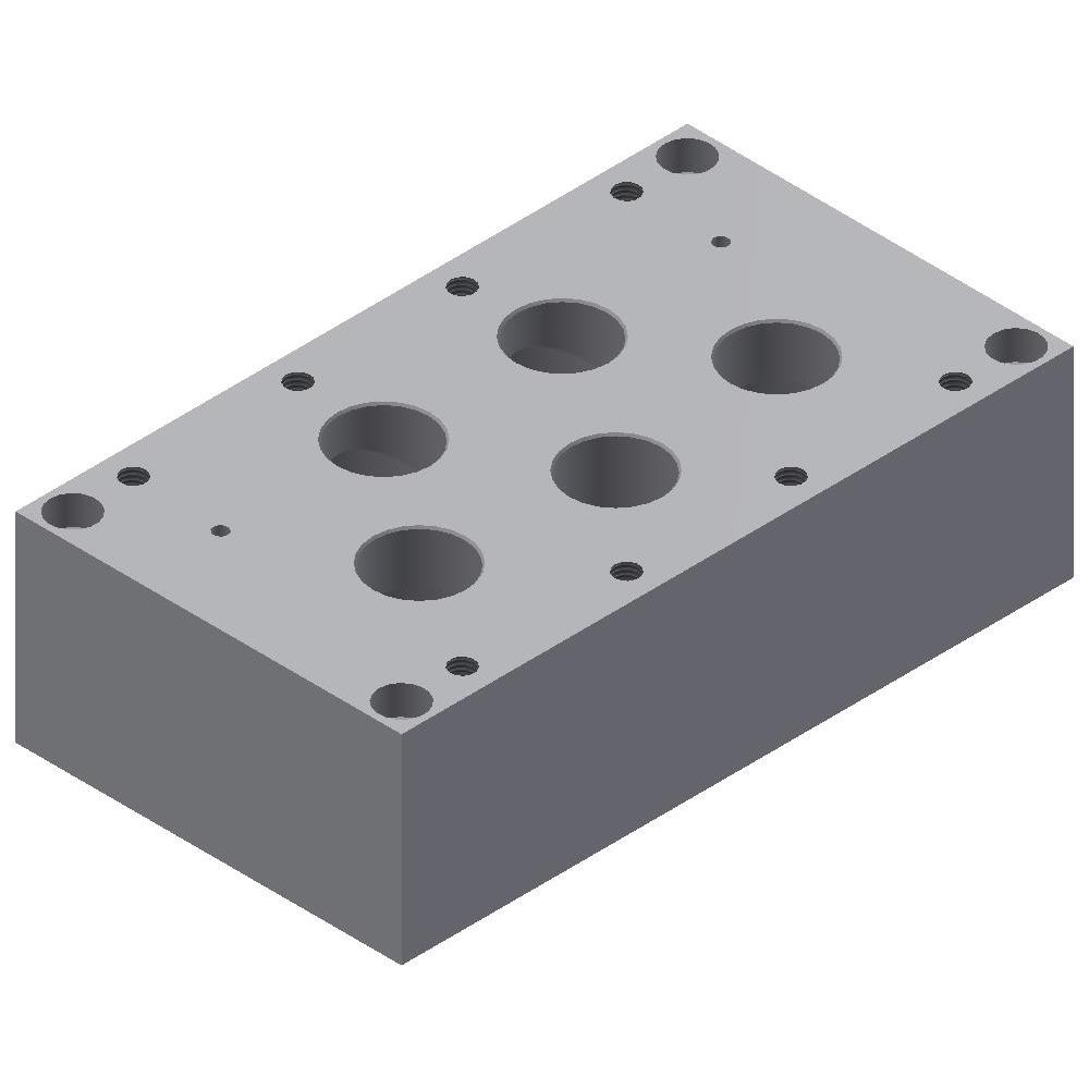
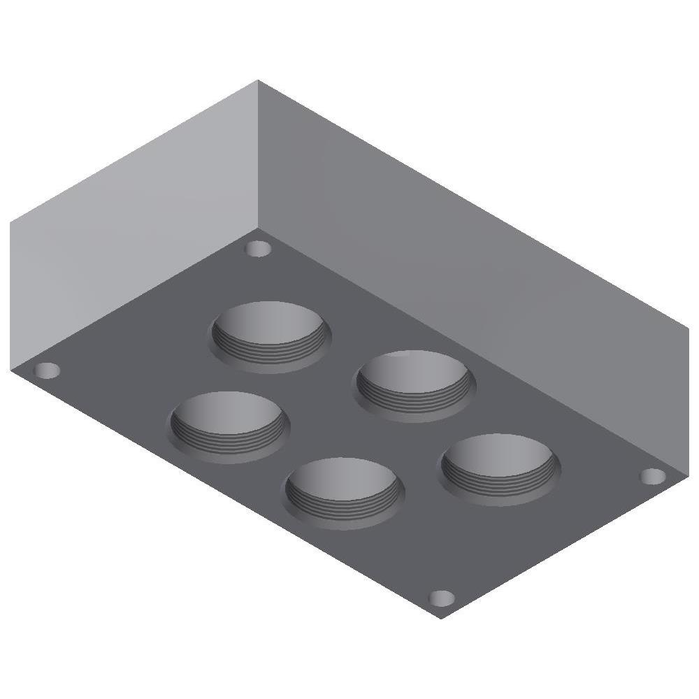
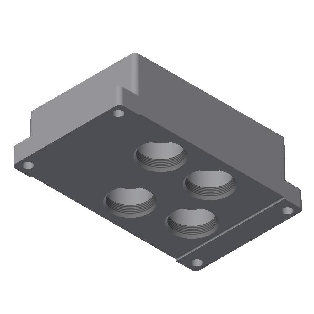
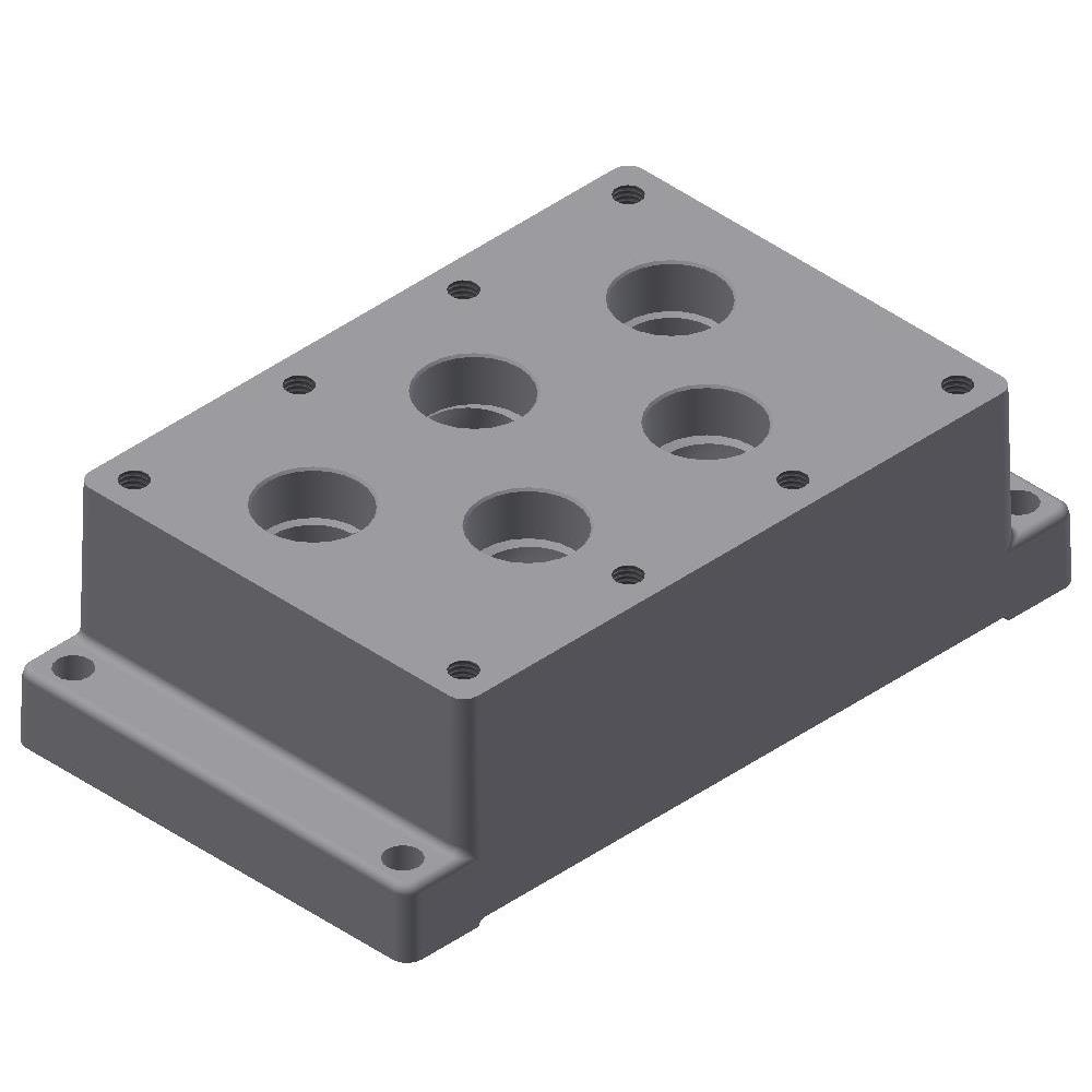
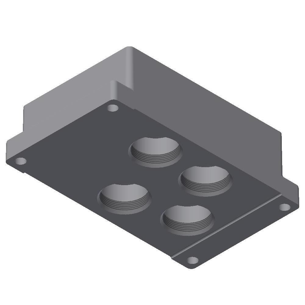
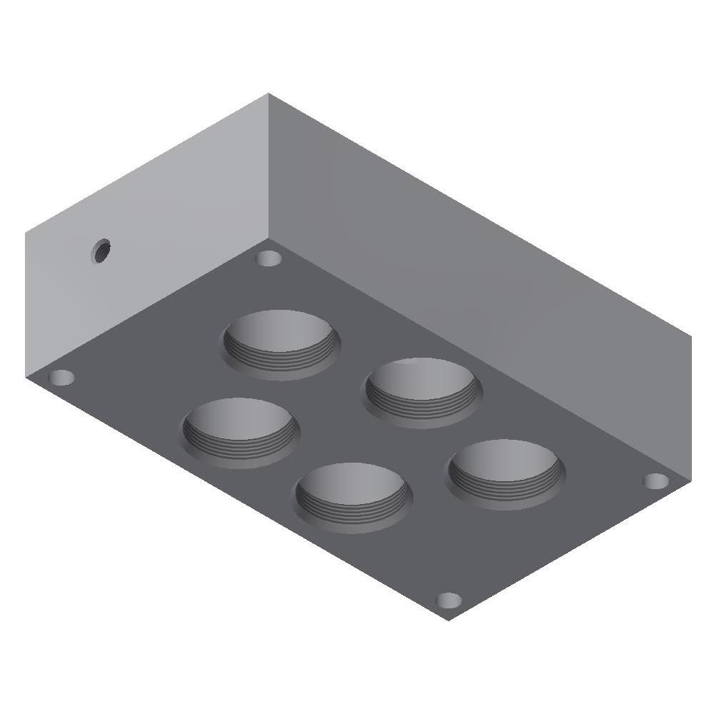
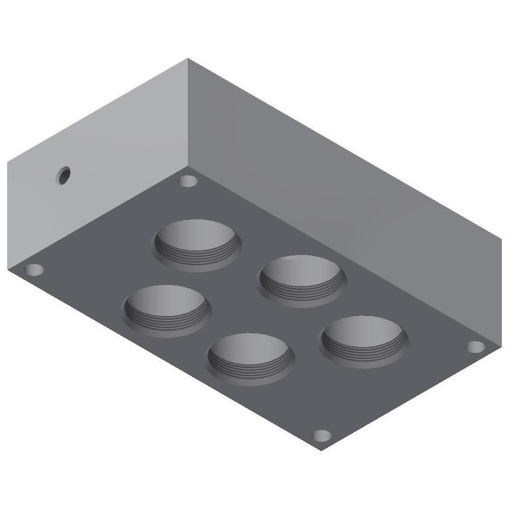
Subplates for 3P Valves - 1/4" Ports
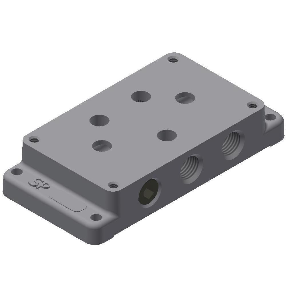
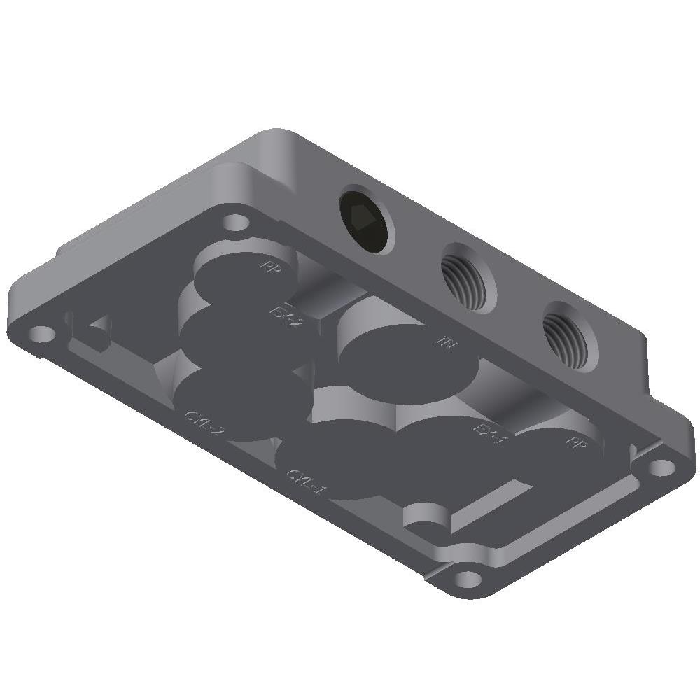
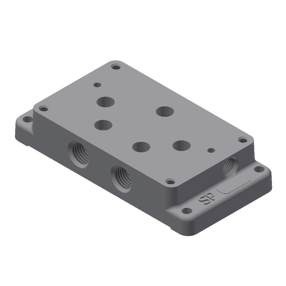
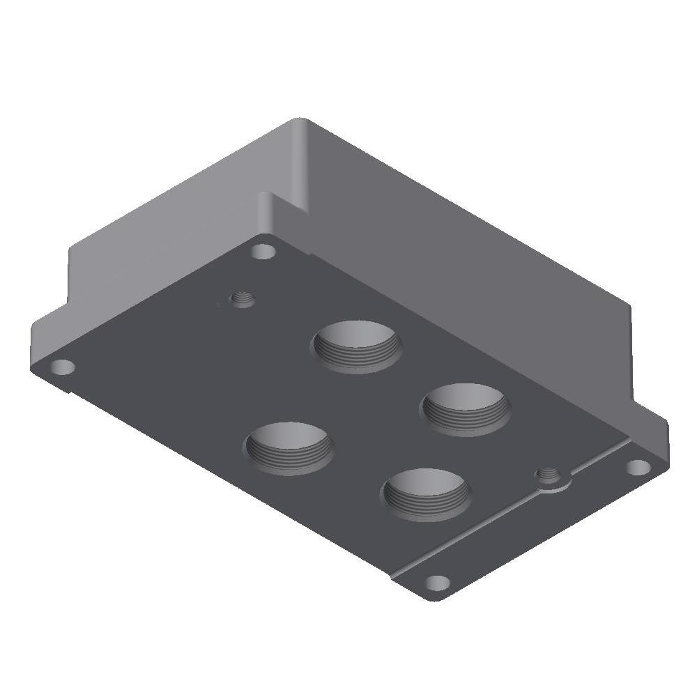
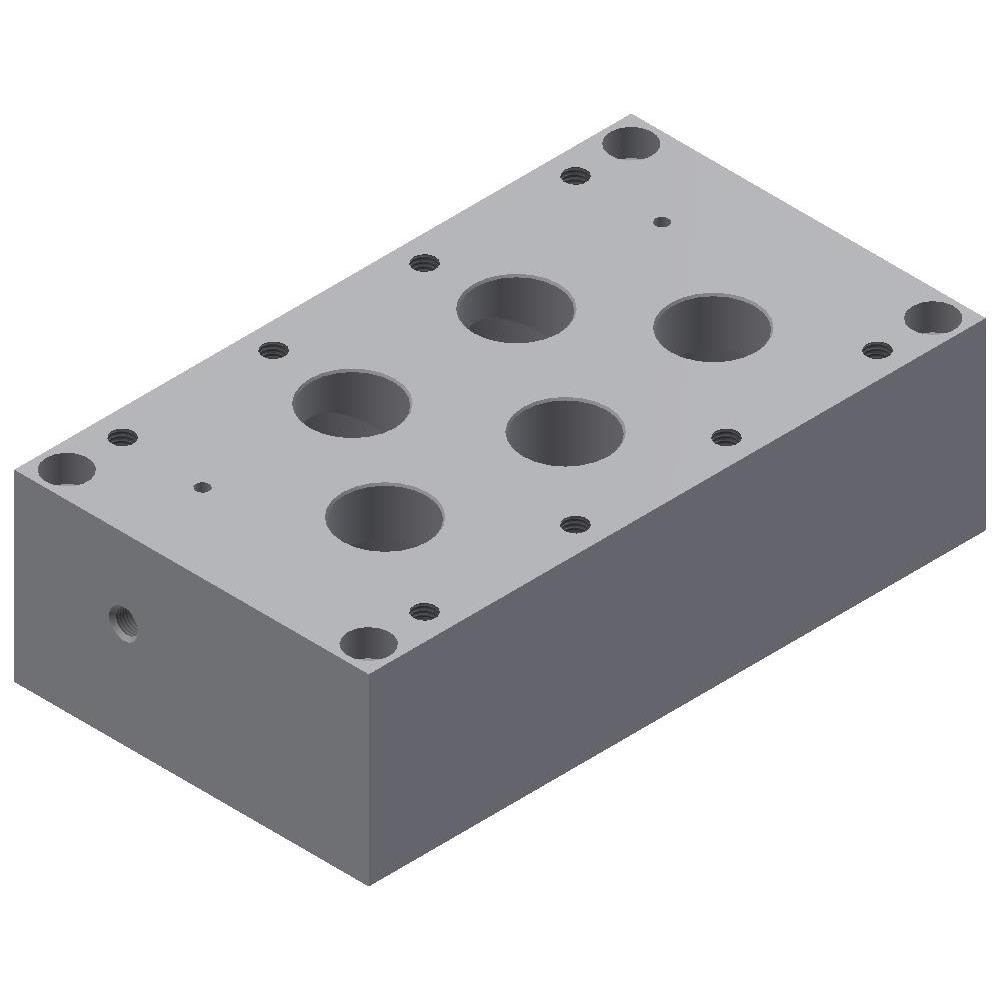
Subplates for 3P Valves - 1/4" Ports with Pilot
Subplates for 3P Valves - 3/8" Ports
Subplates for 3P Valves - 3/8" Ports with Pilot
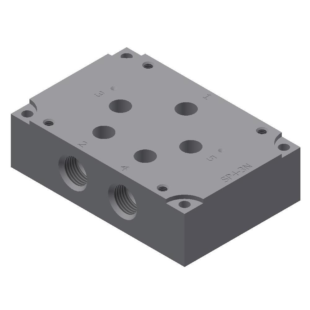
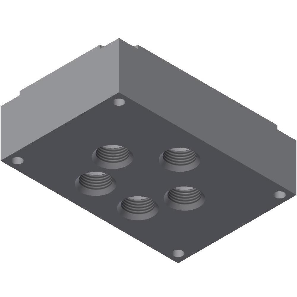
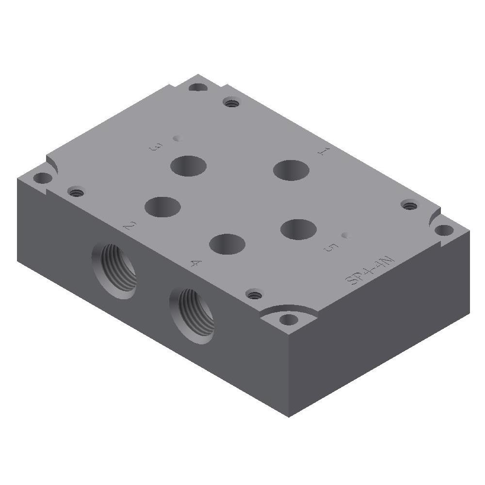
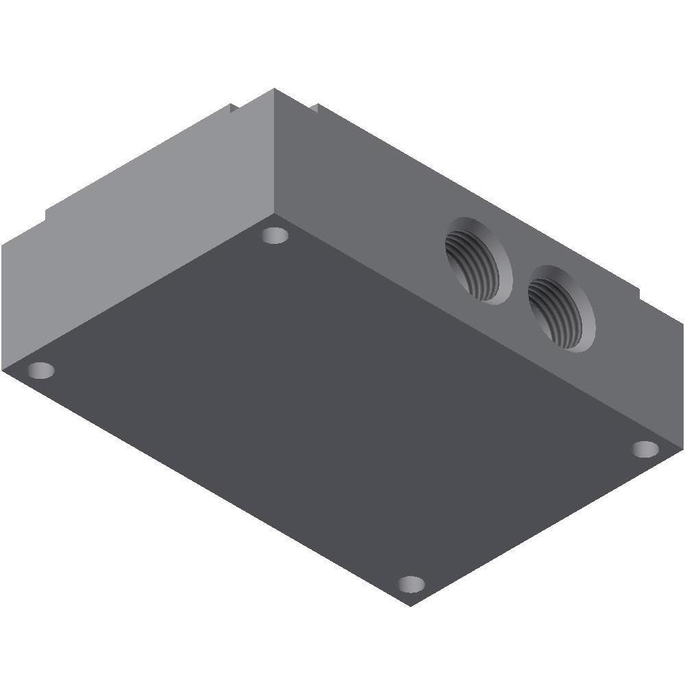
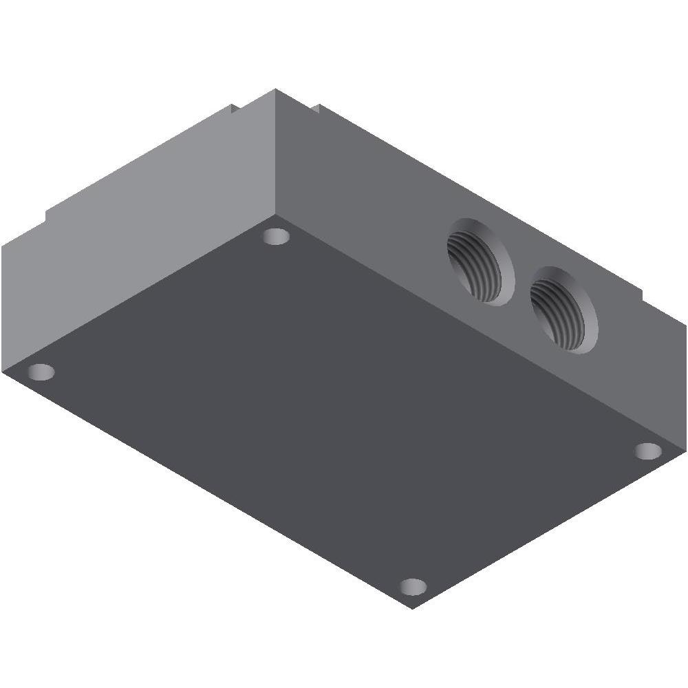
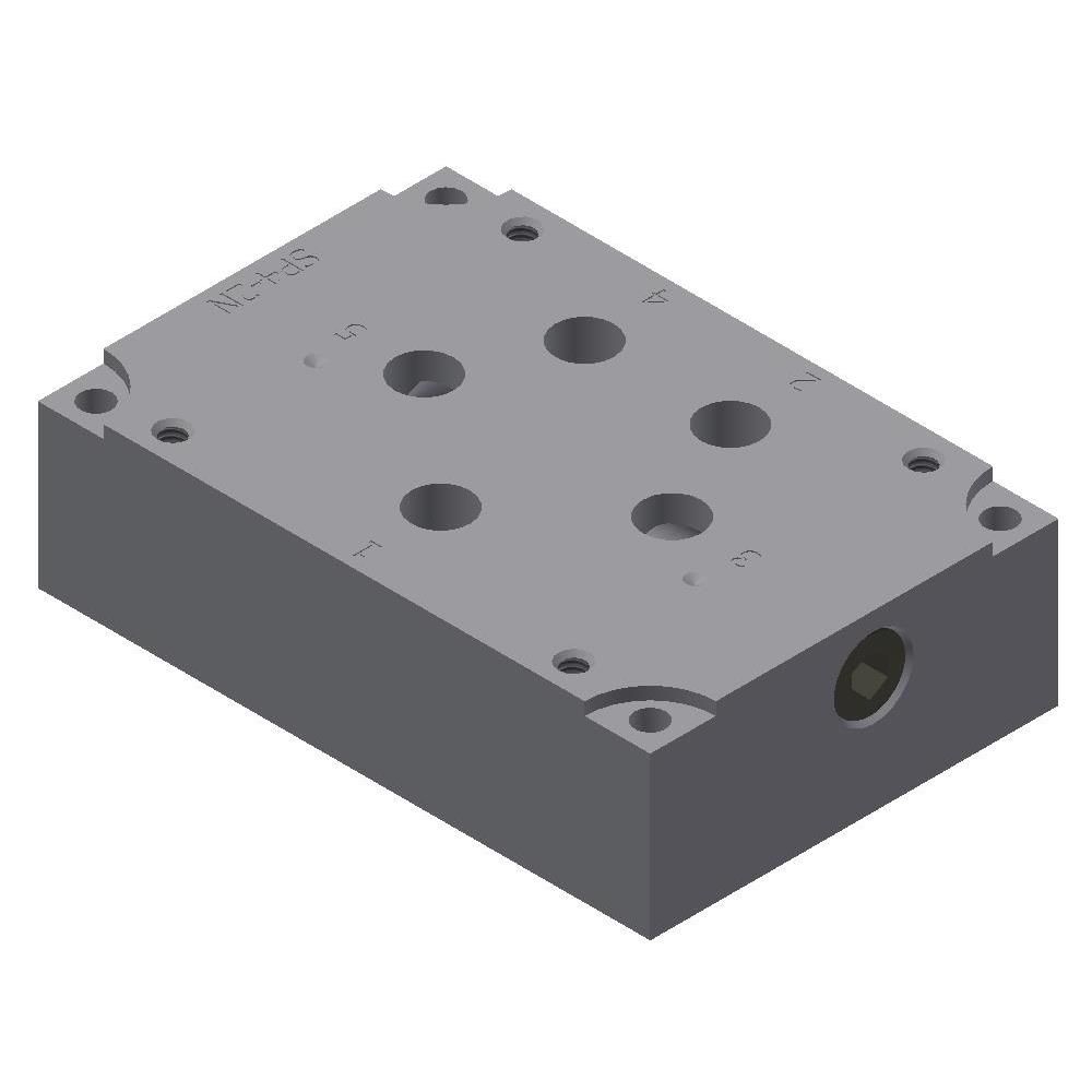
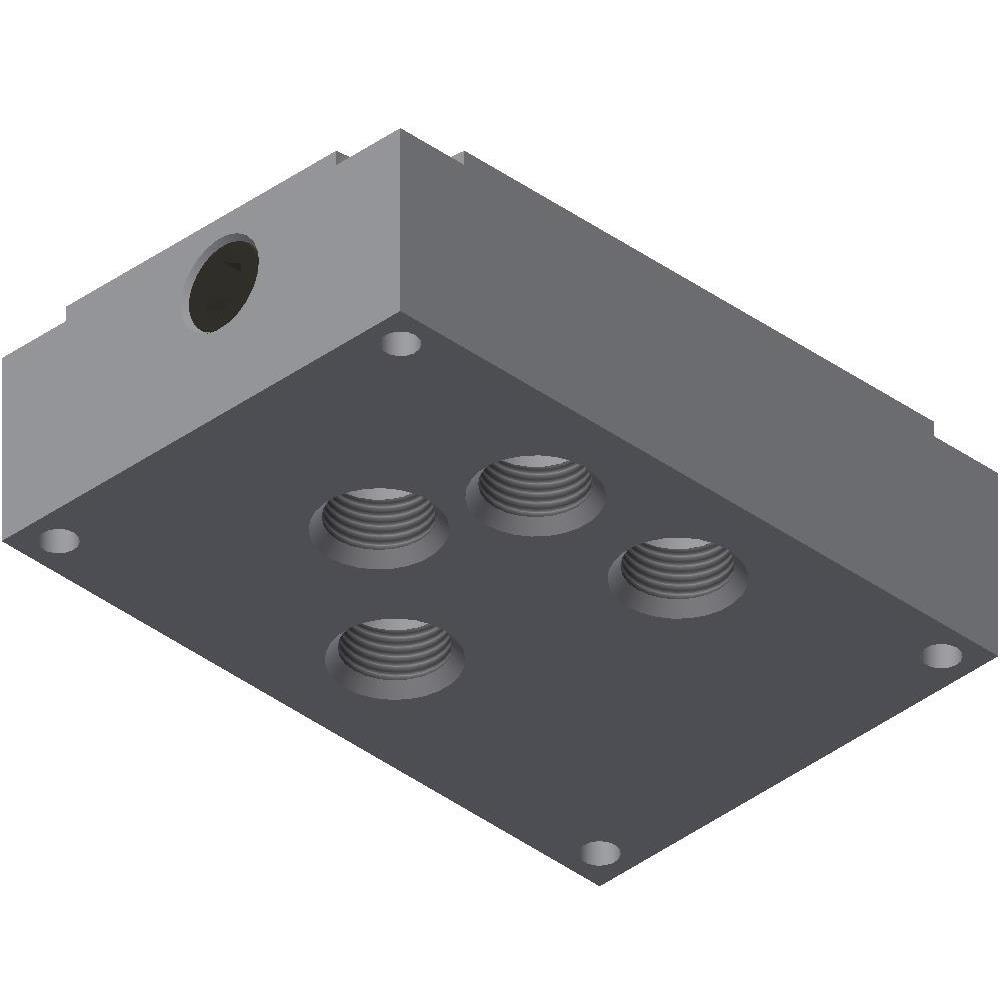
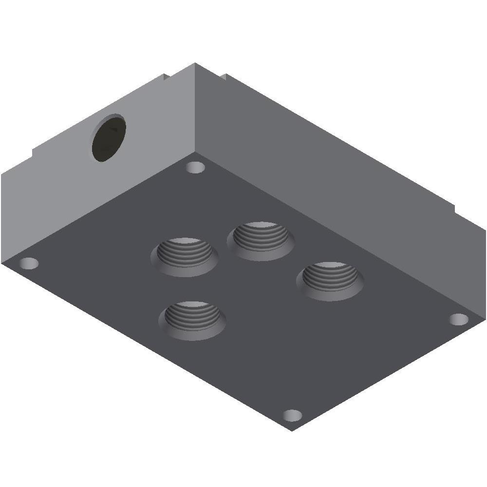
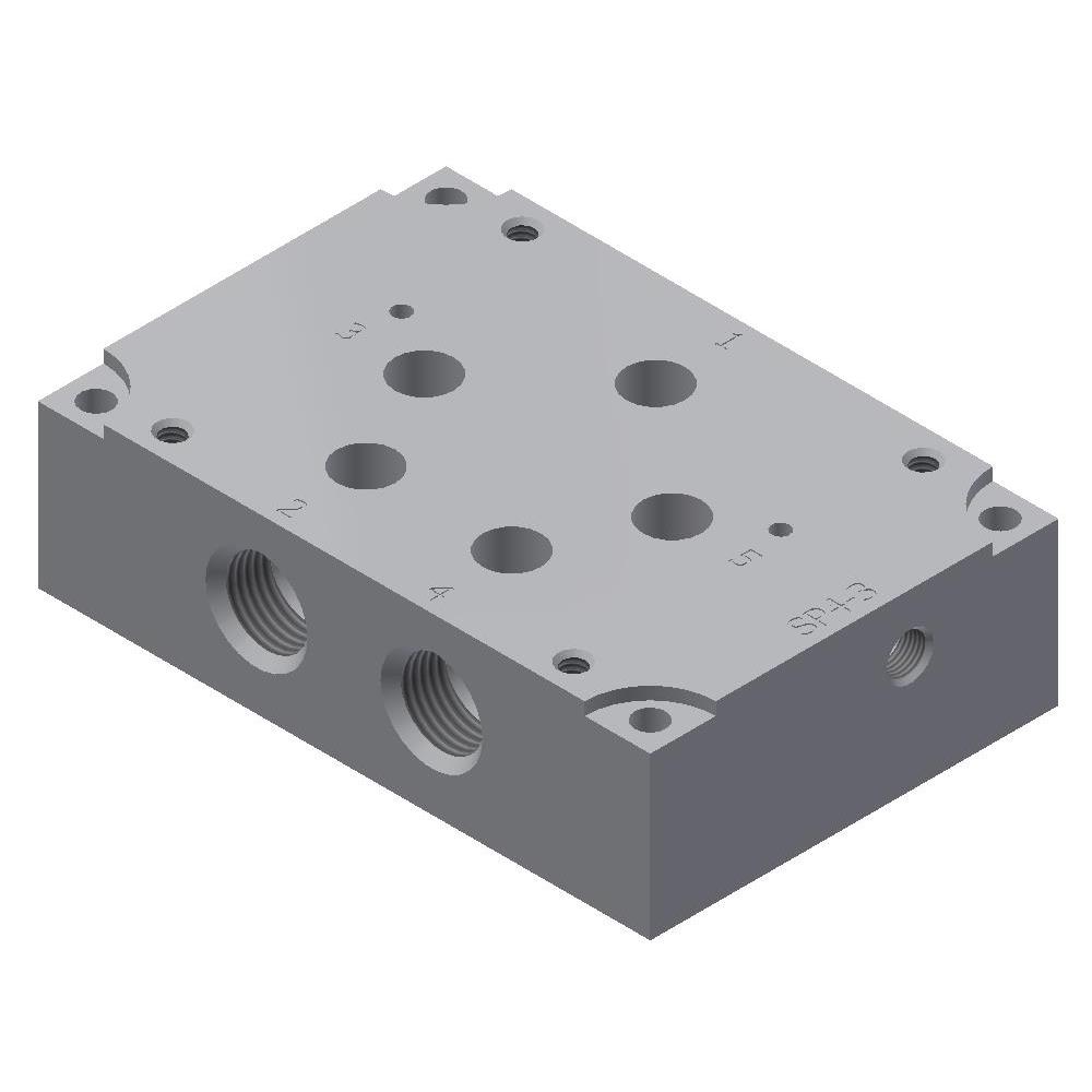
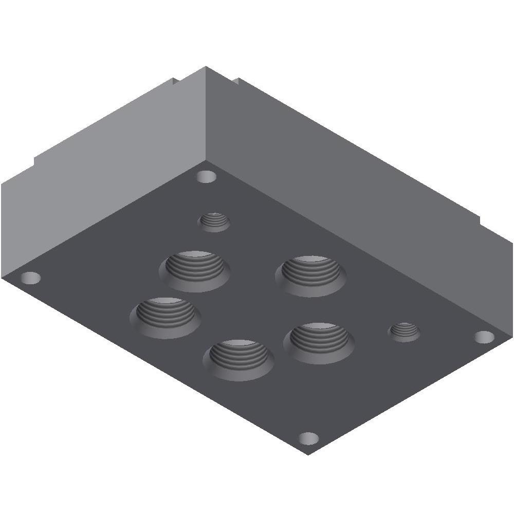
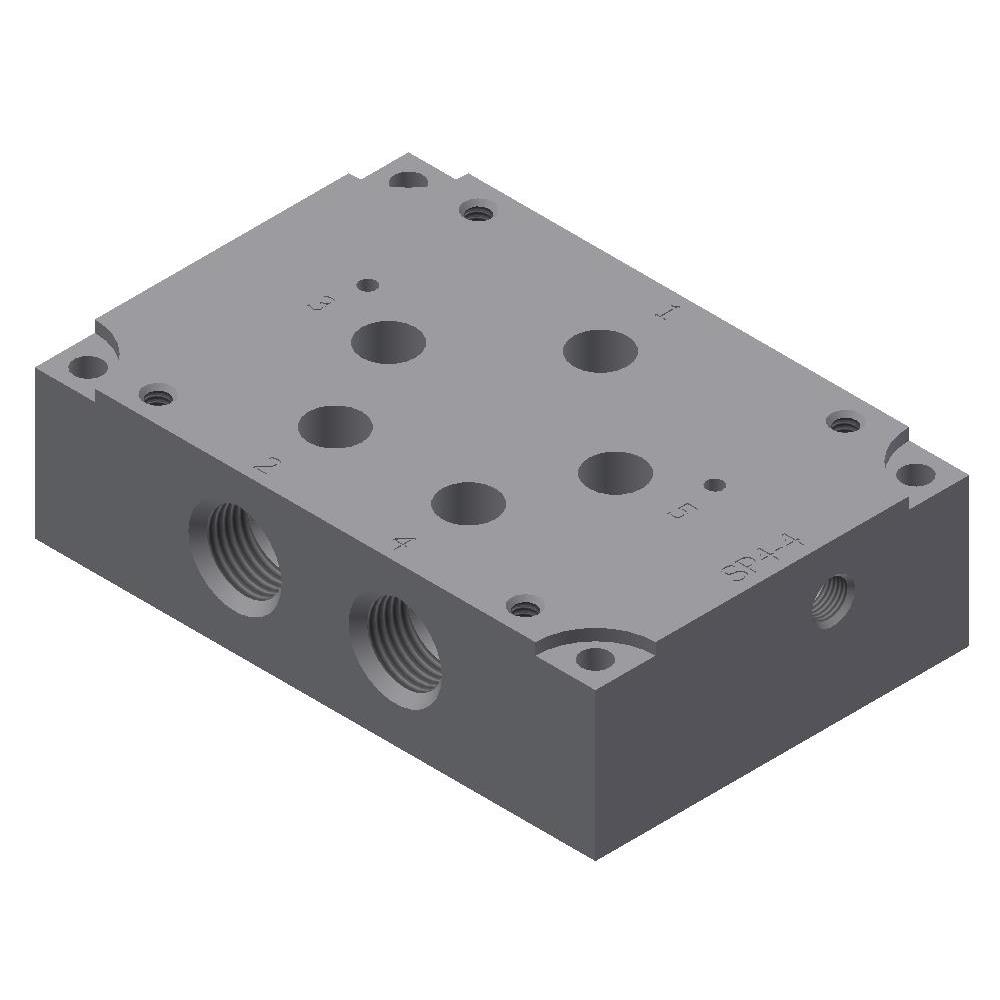
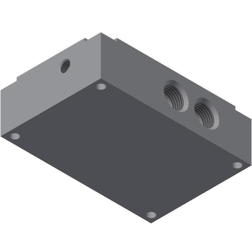
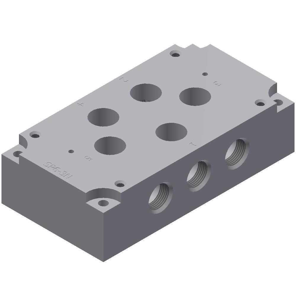
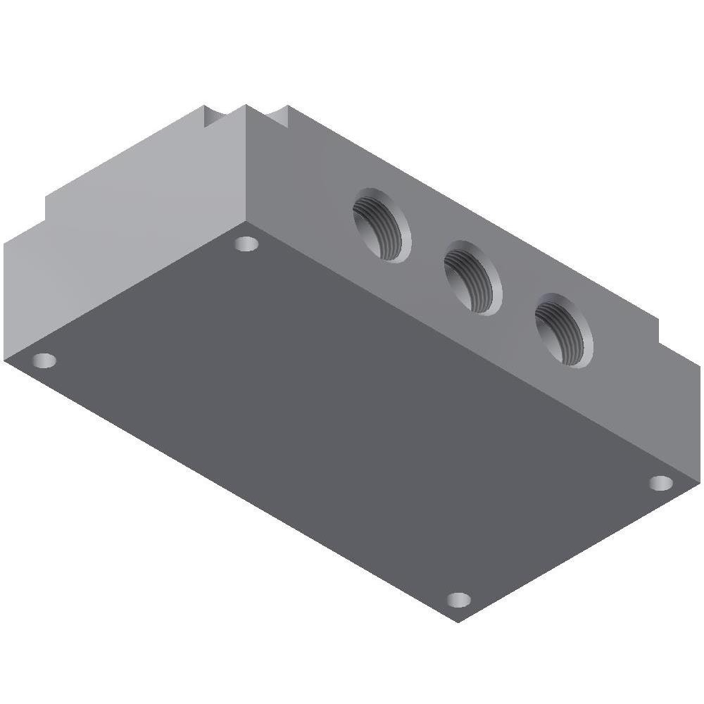
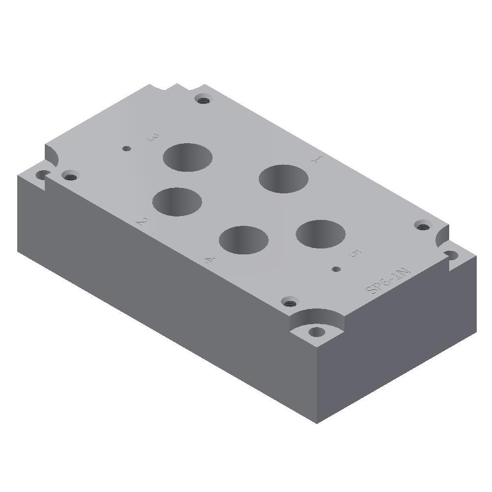
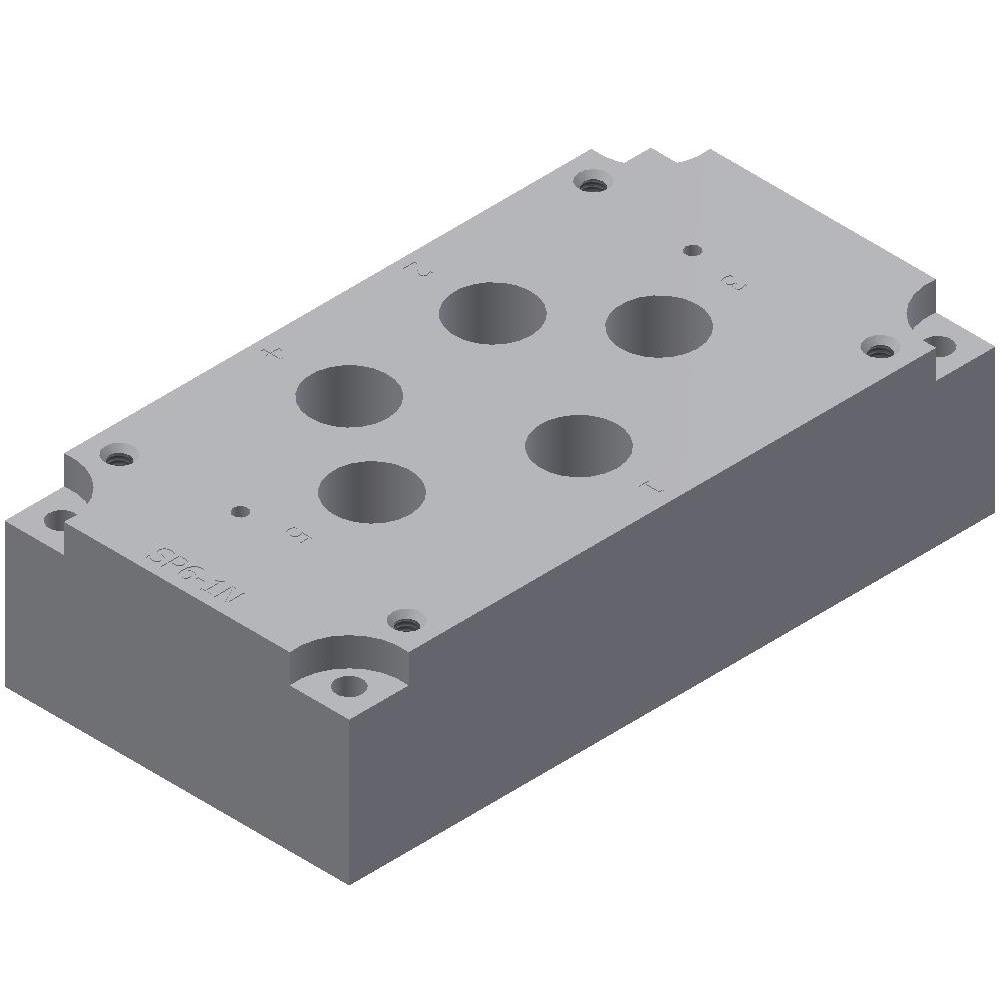
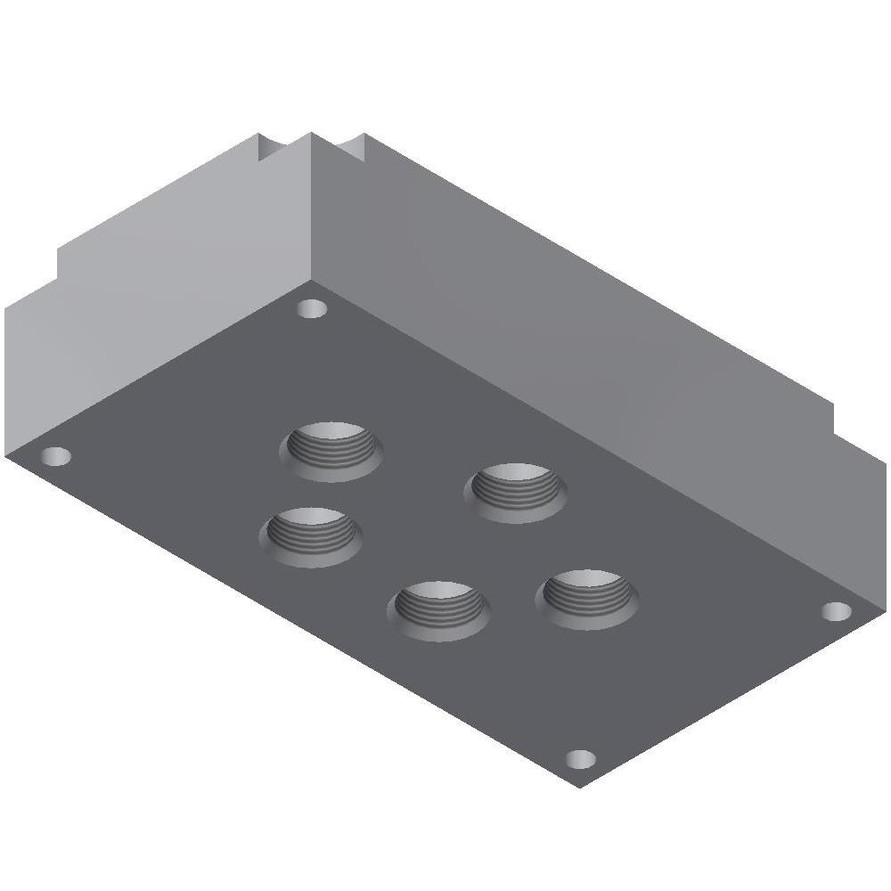
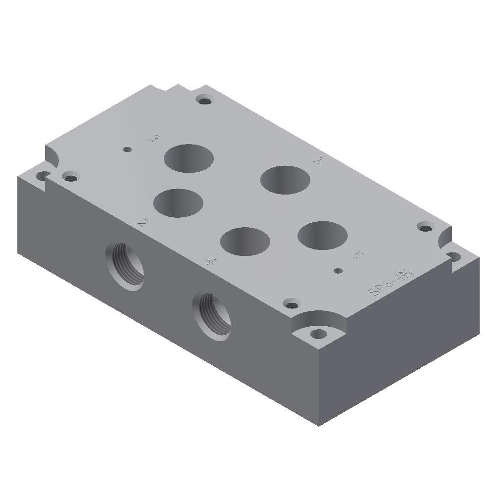
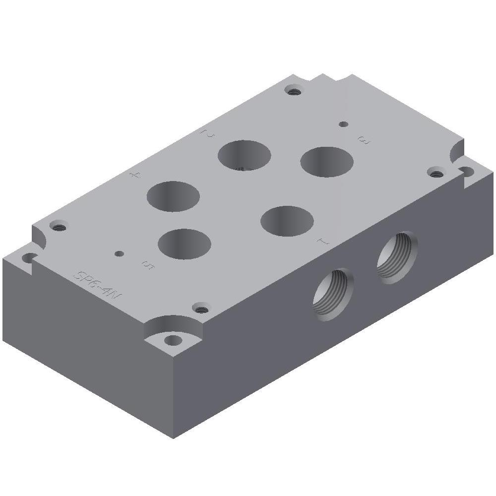
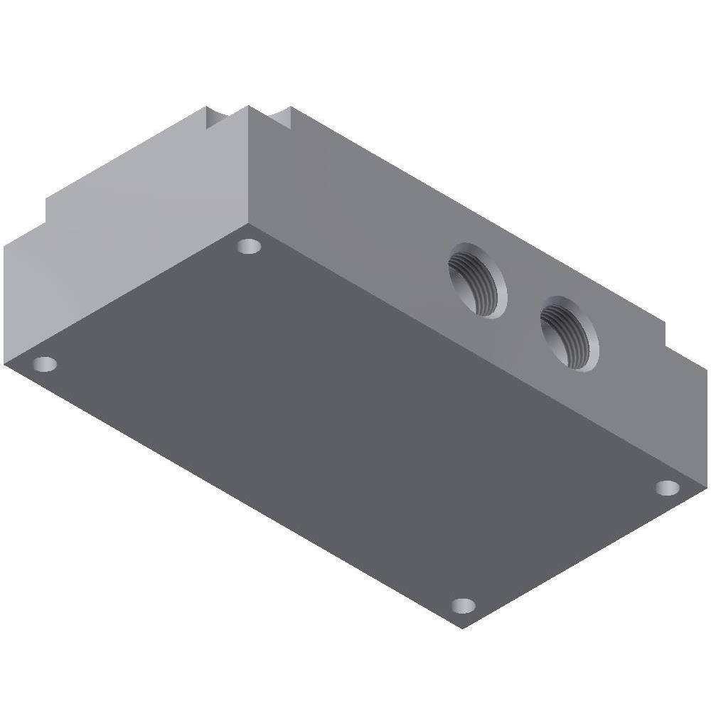
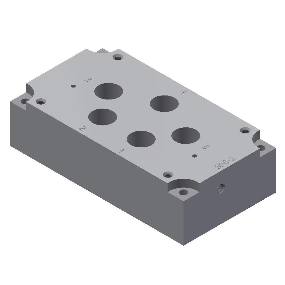
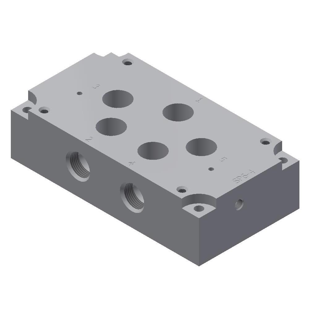
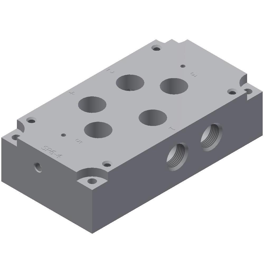
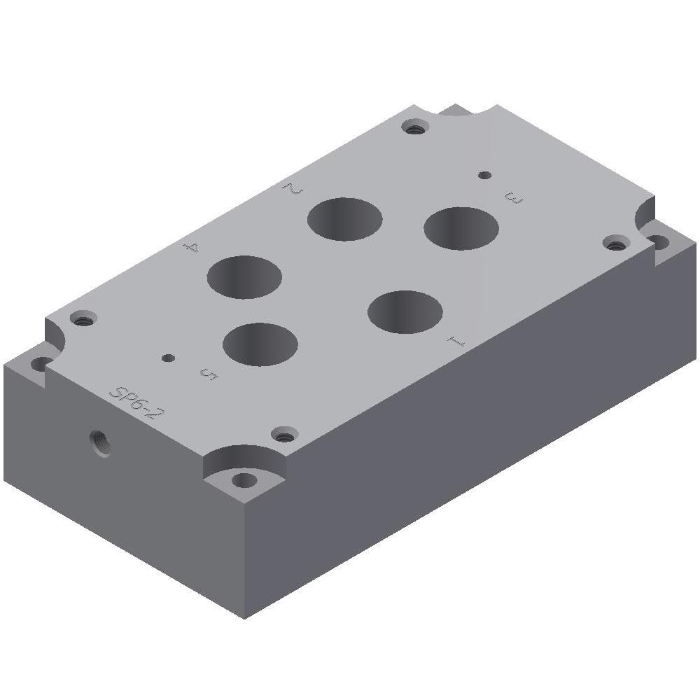
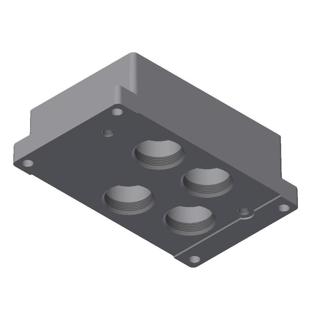
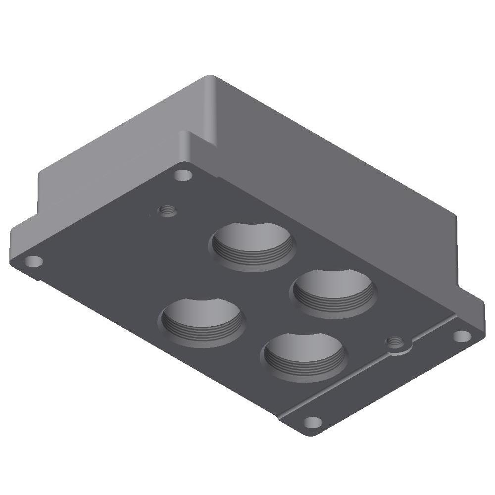
Subplates for 4P Valves - 1/2" Ports
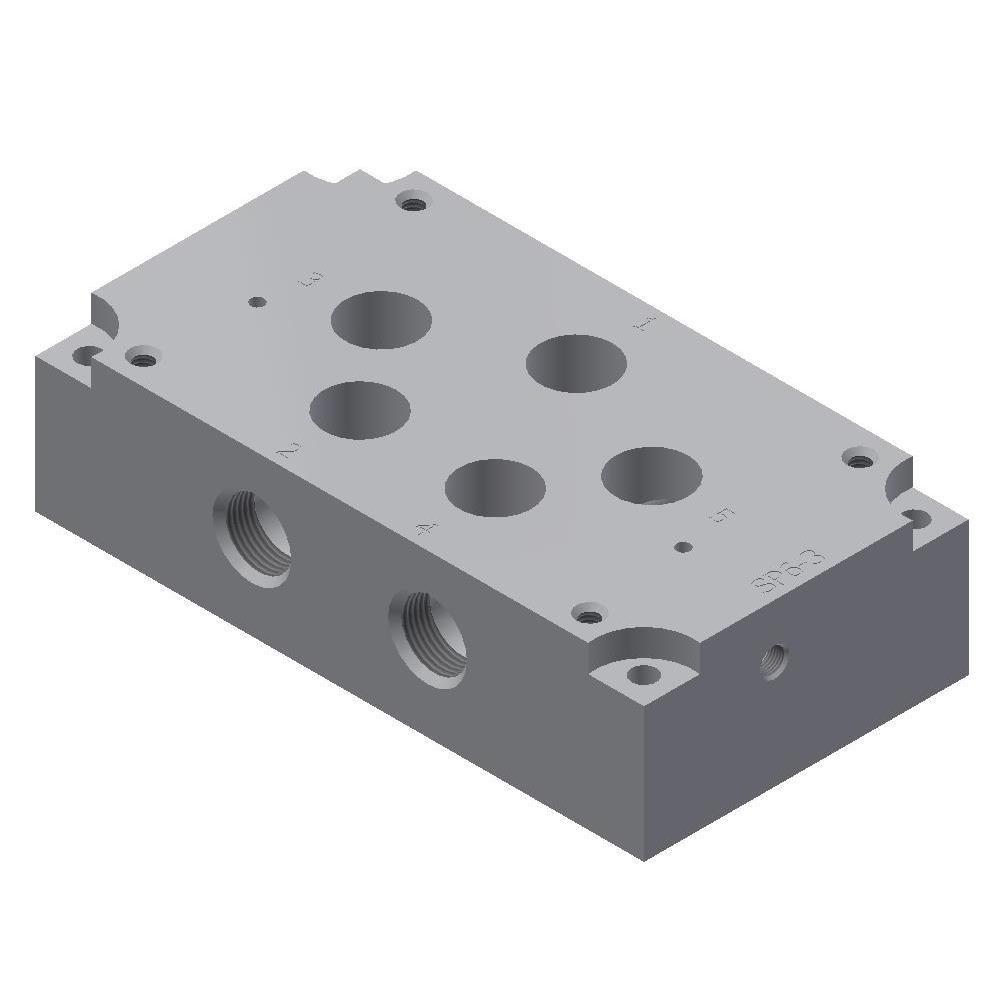
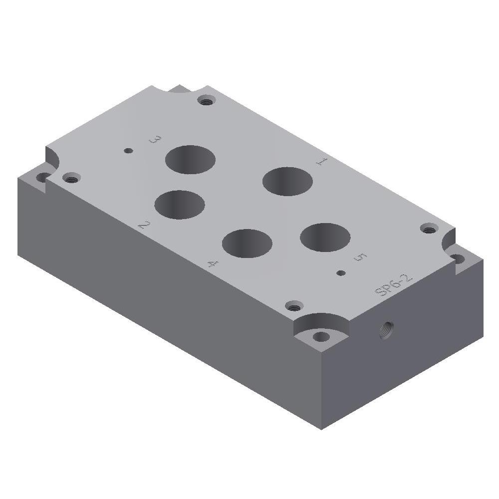
Subplates for 4P Valves - 1/2" Ports with Pilot
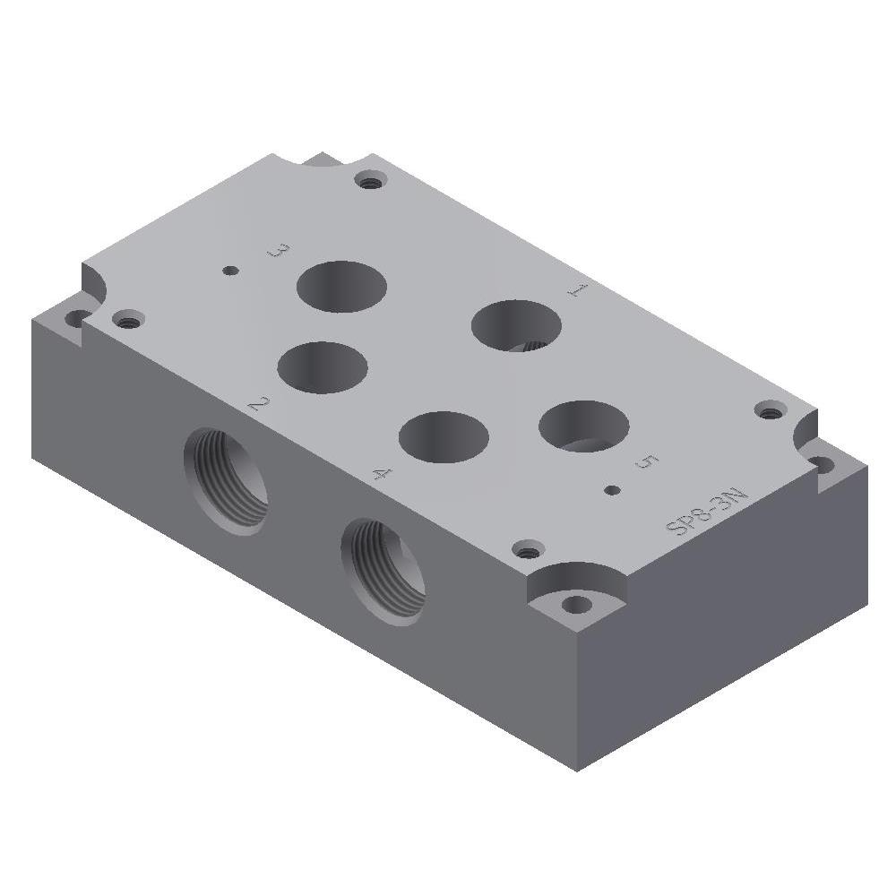
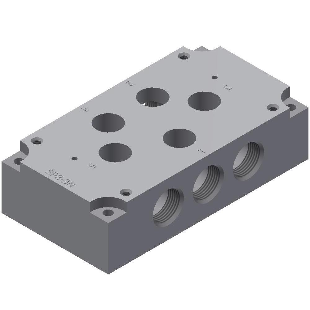
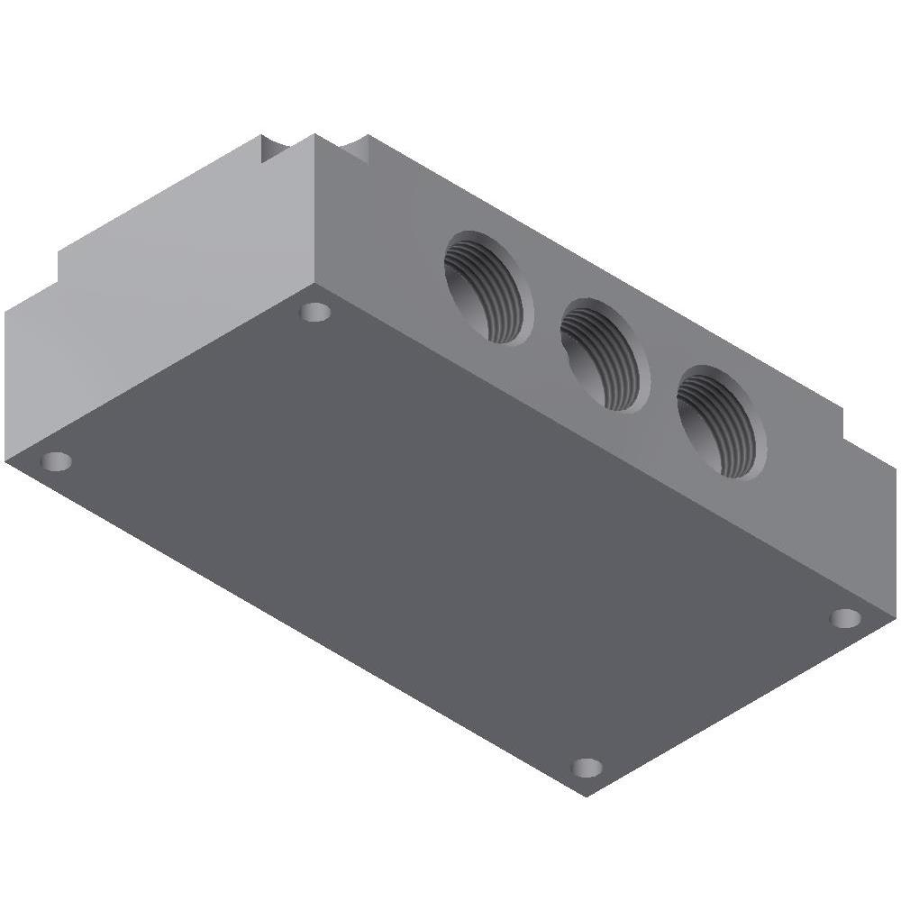
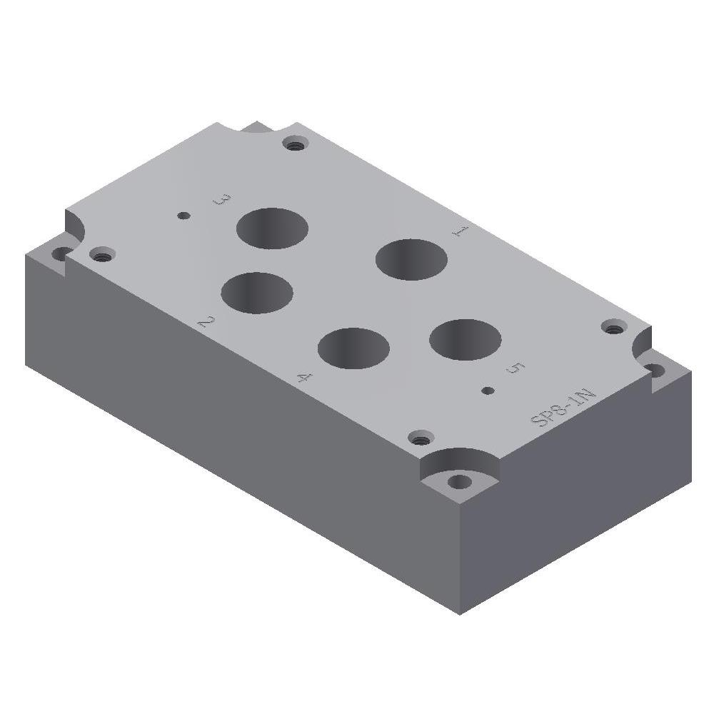
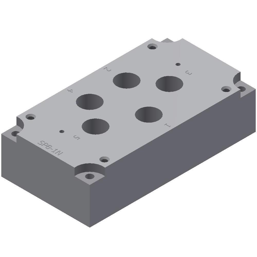
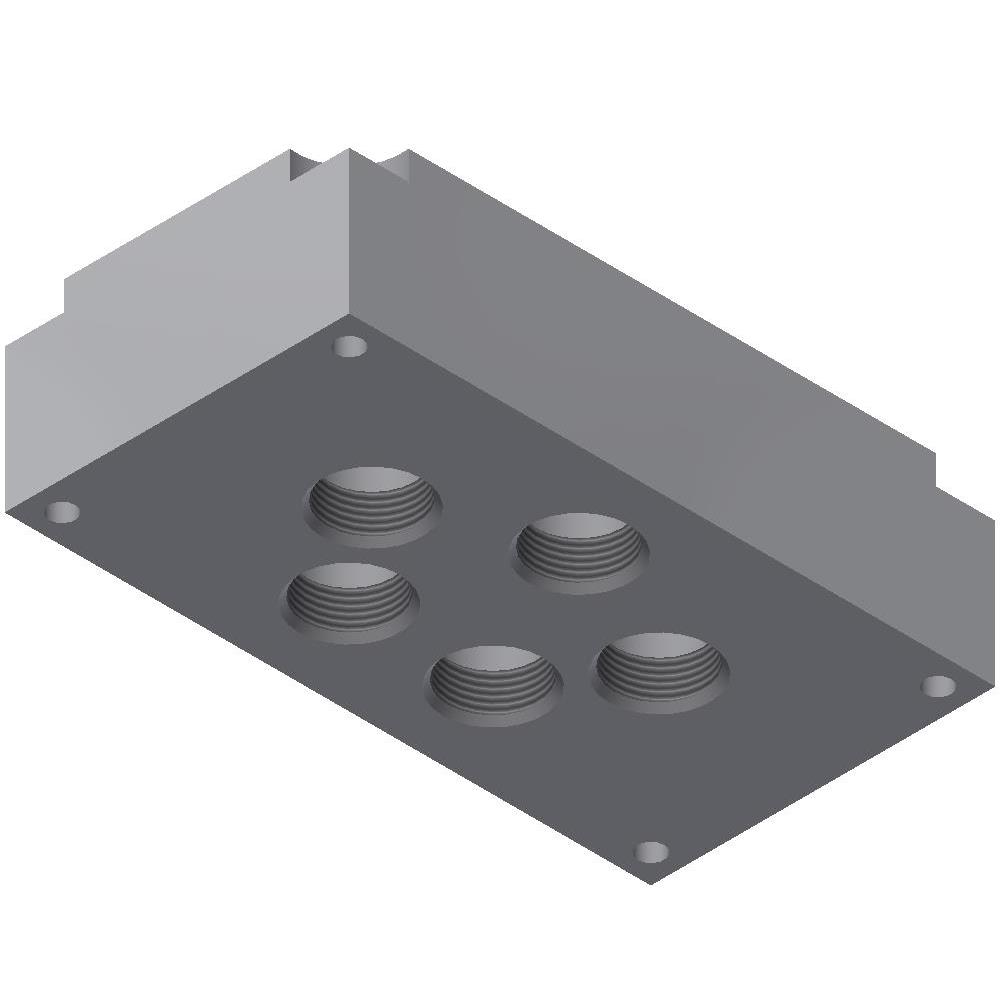
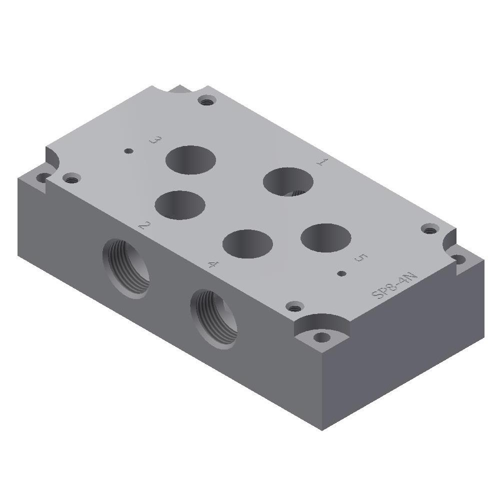
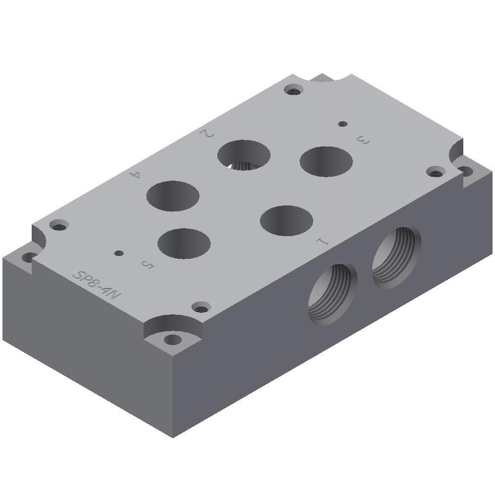
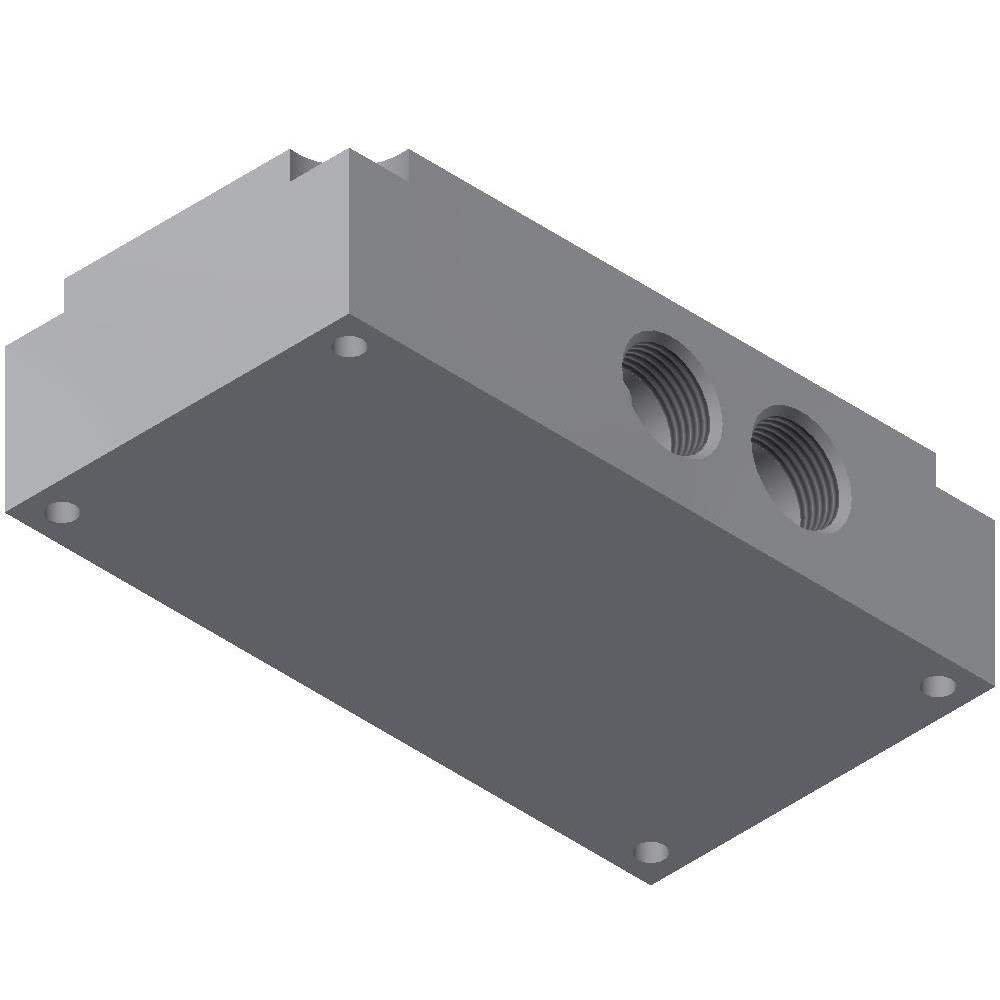
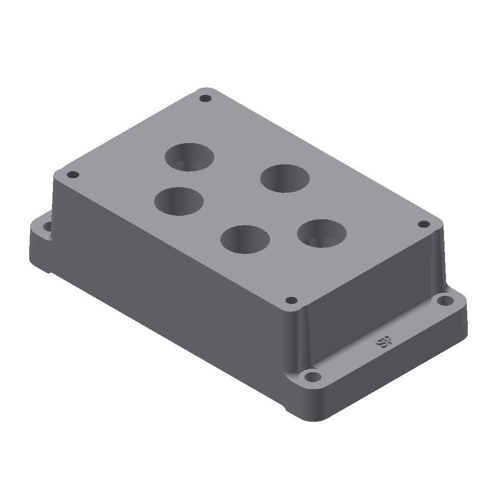
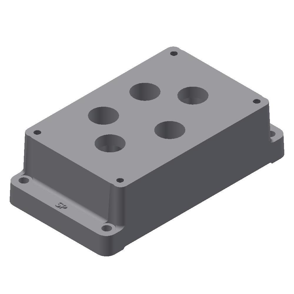
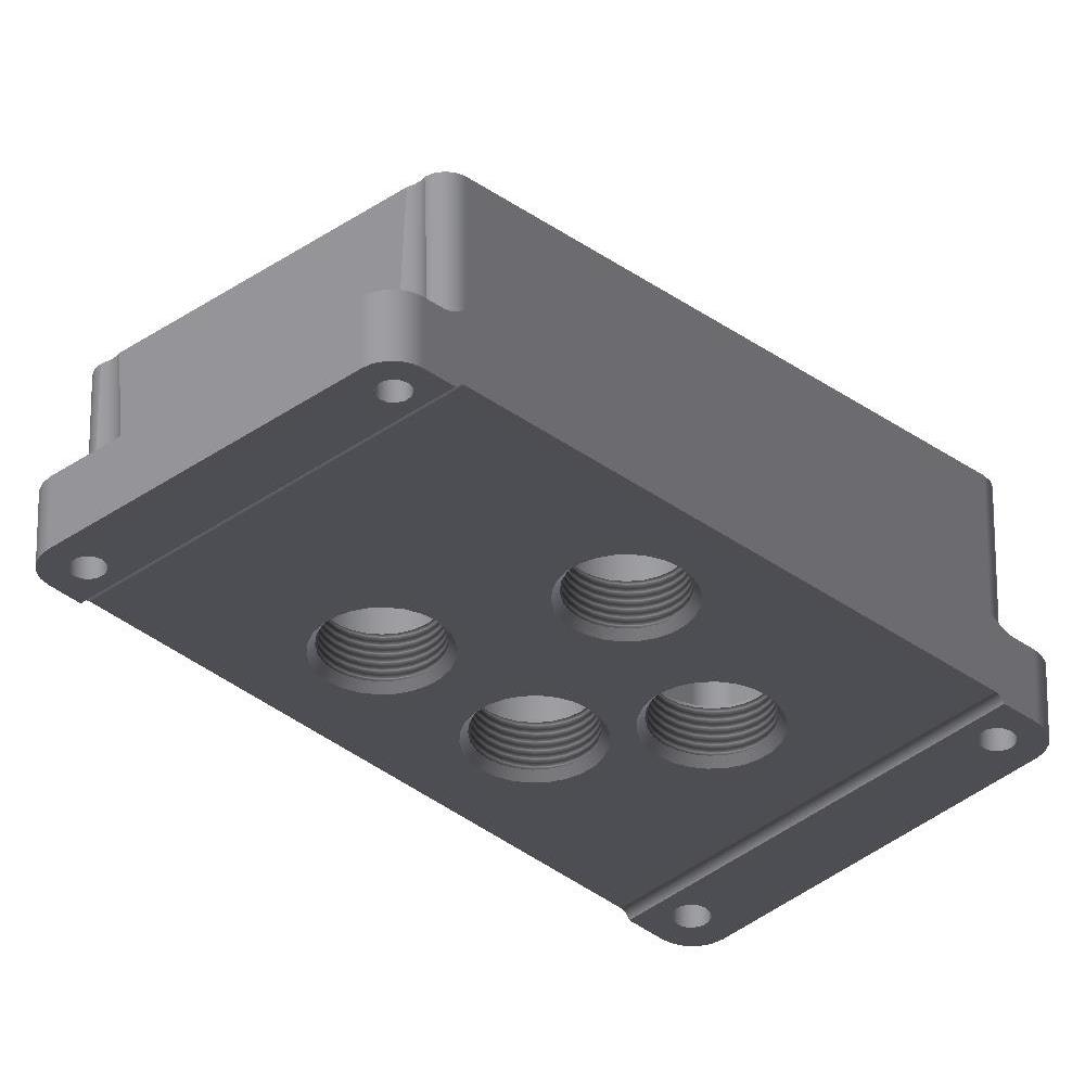
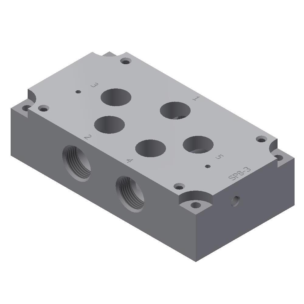
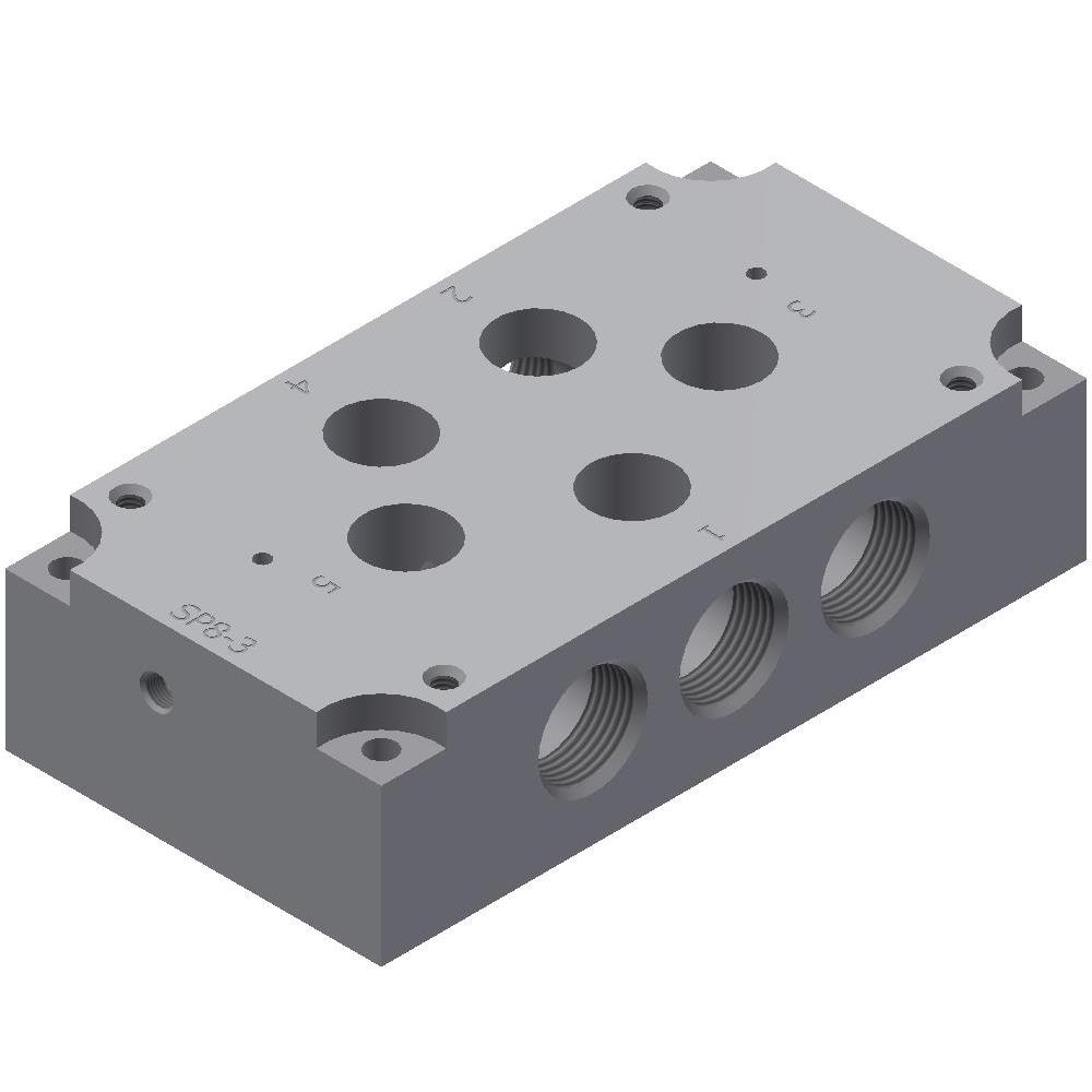
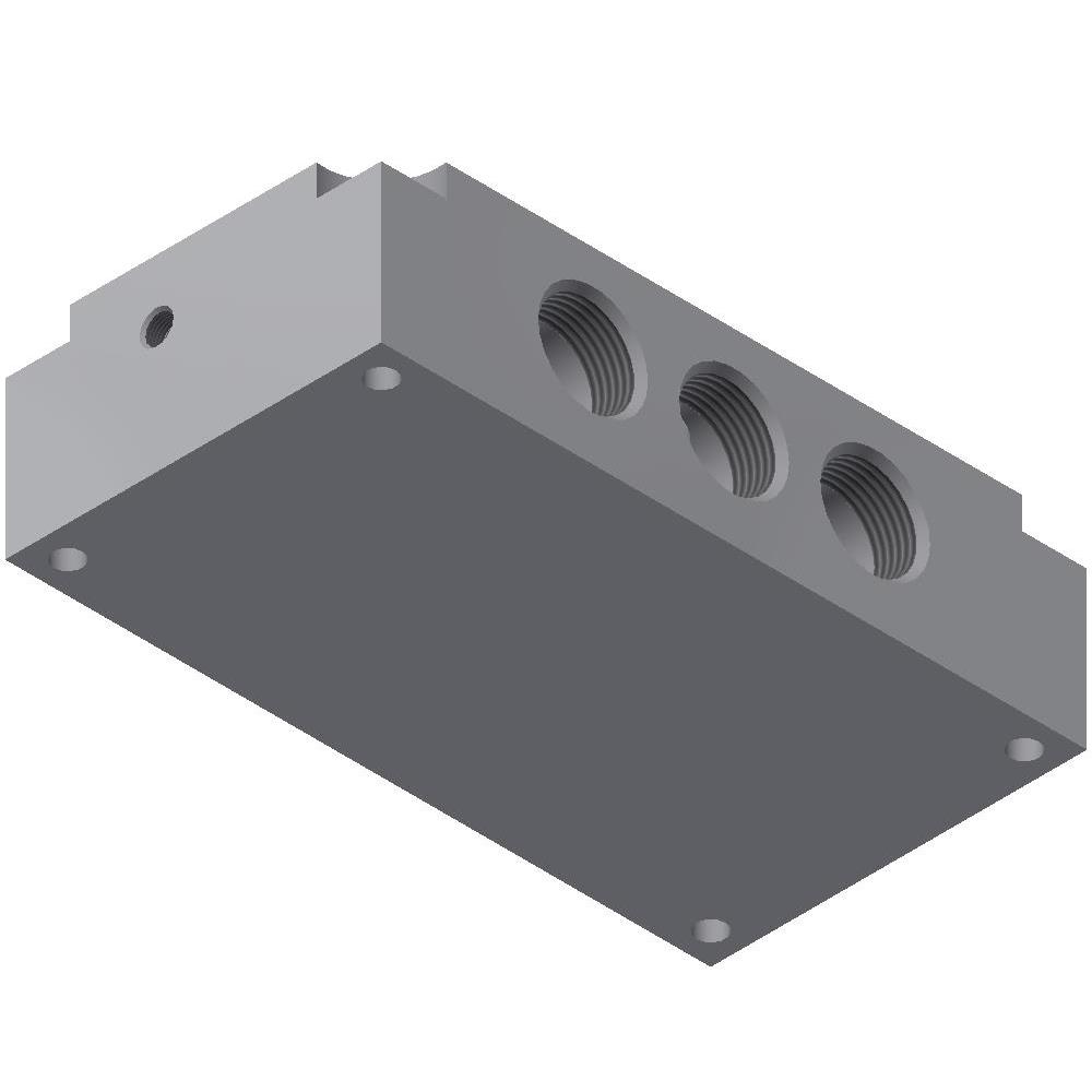
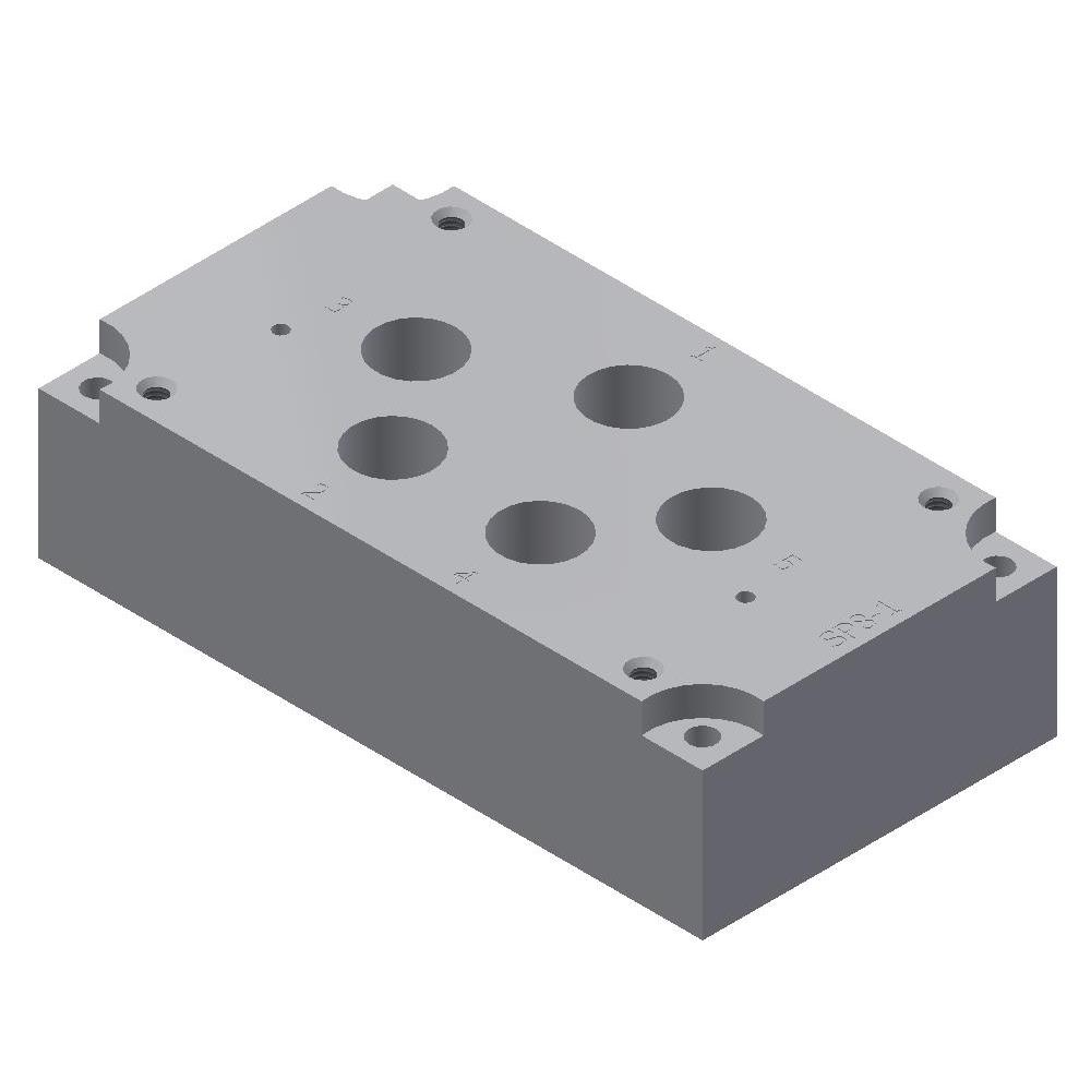
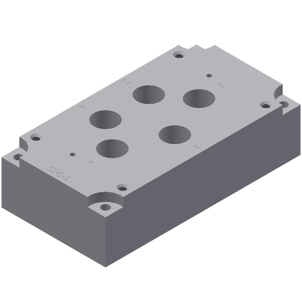
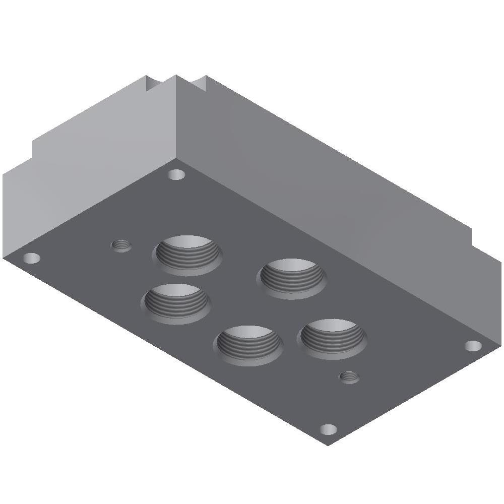
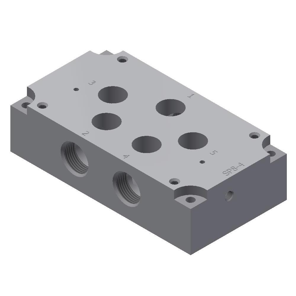
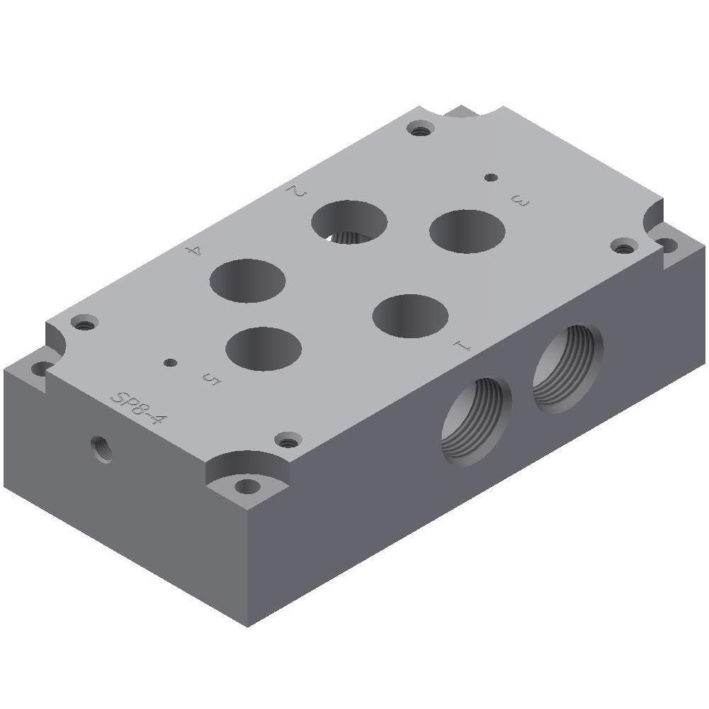
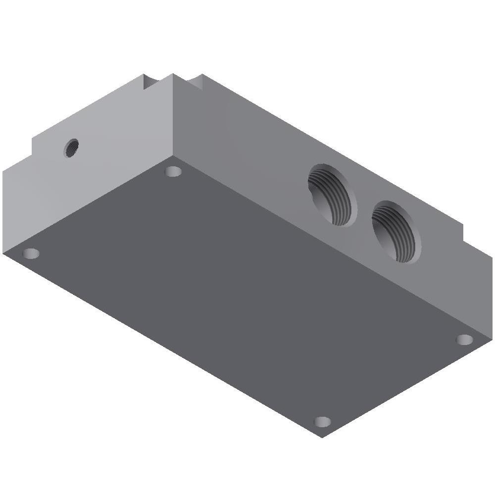
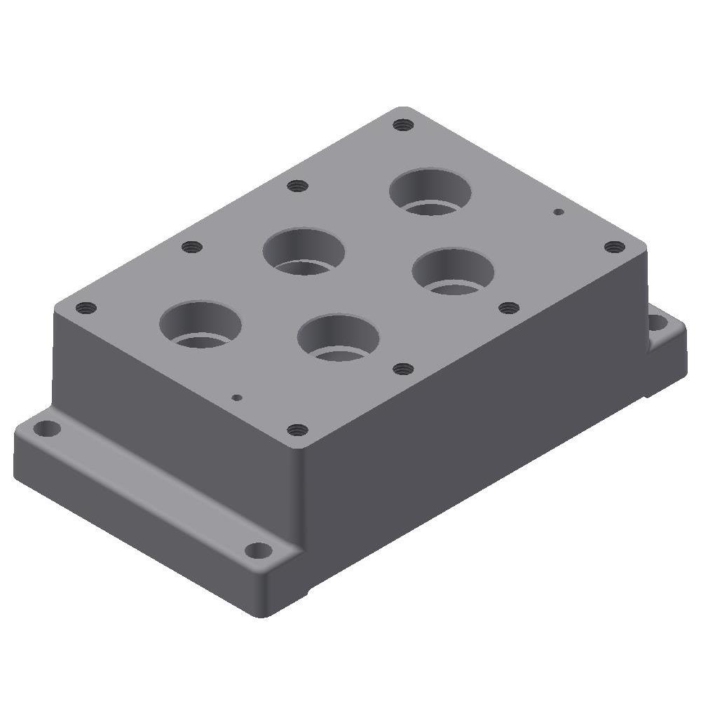
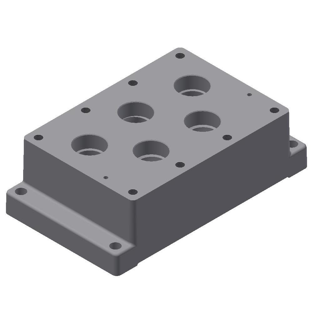
Subplates for 8P Valves - 1" Ports
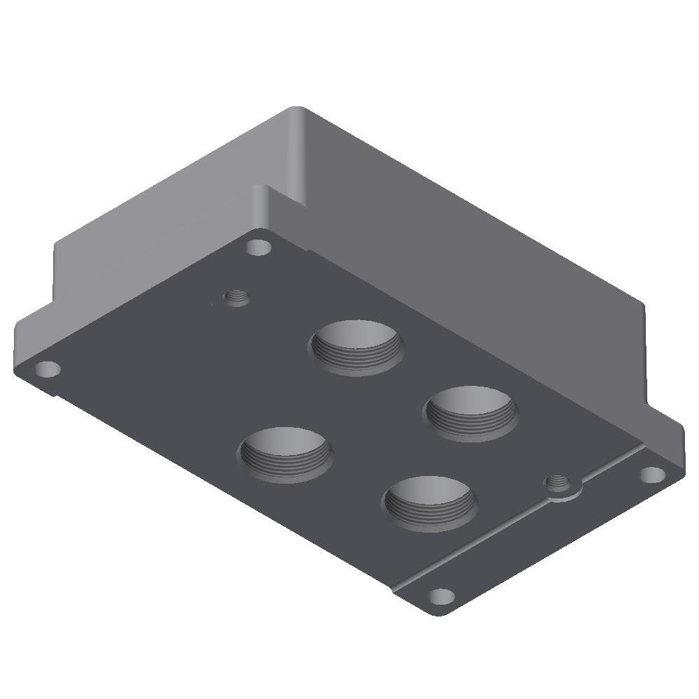
Subplates for 8P Valves - 1" Ports with Pilot
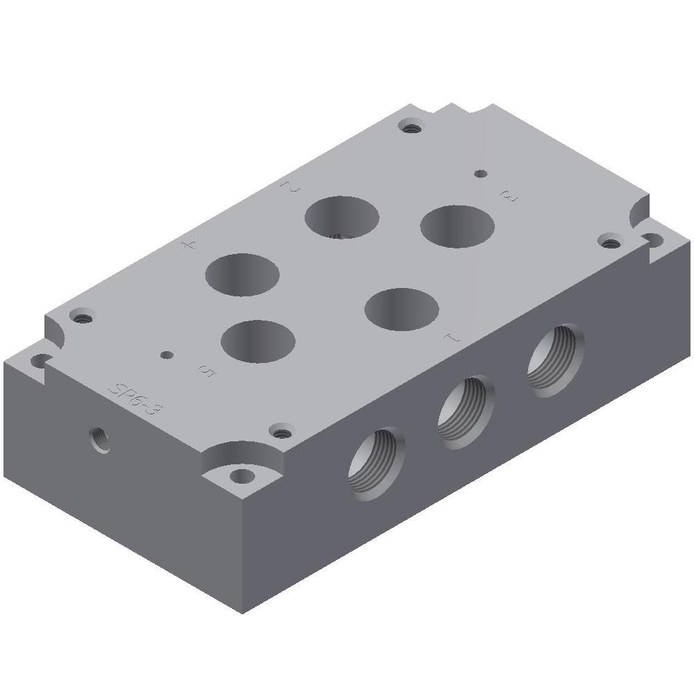
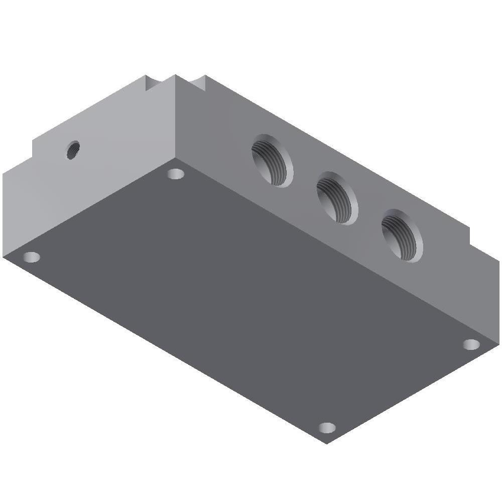
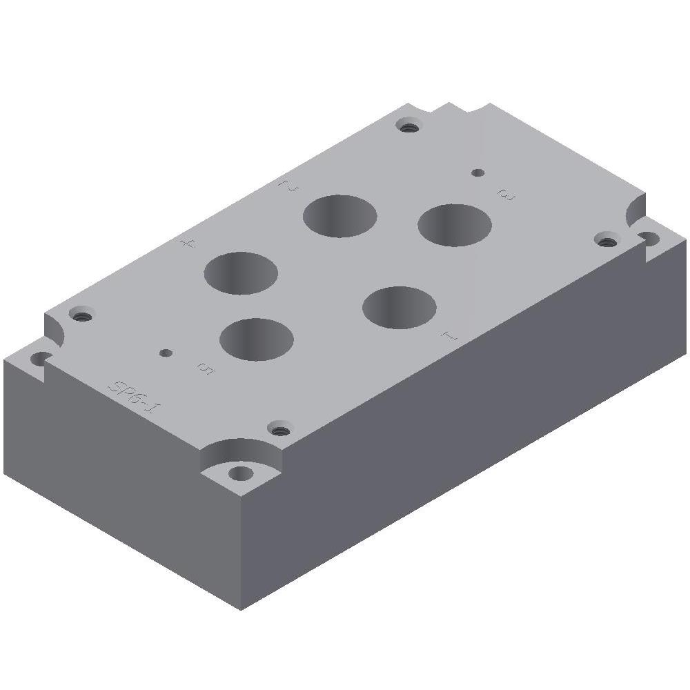
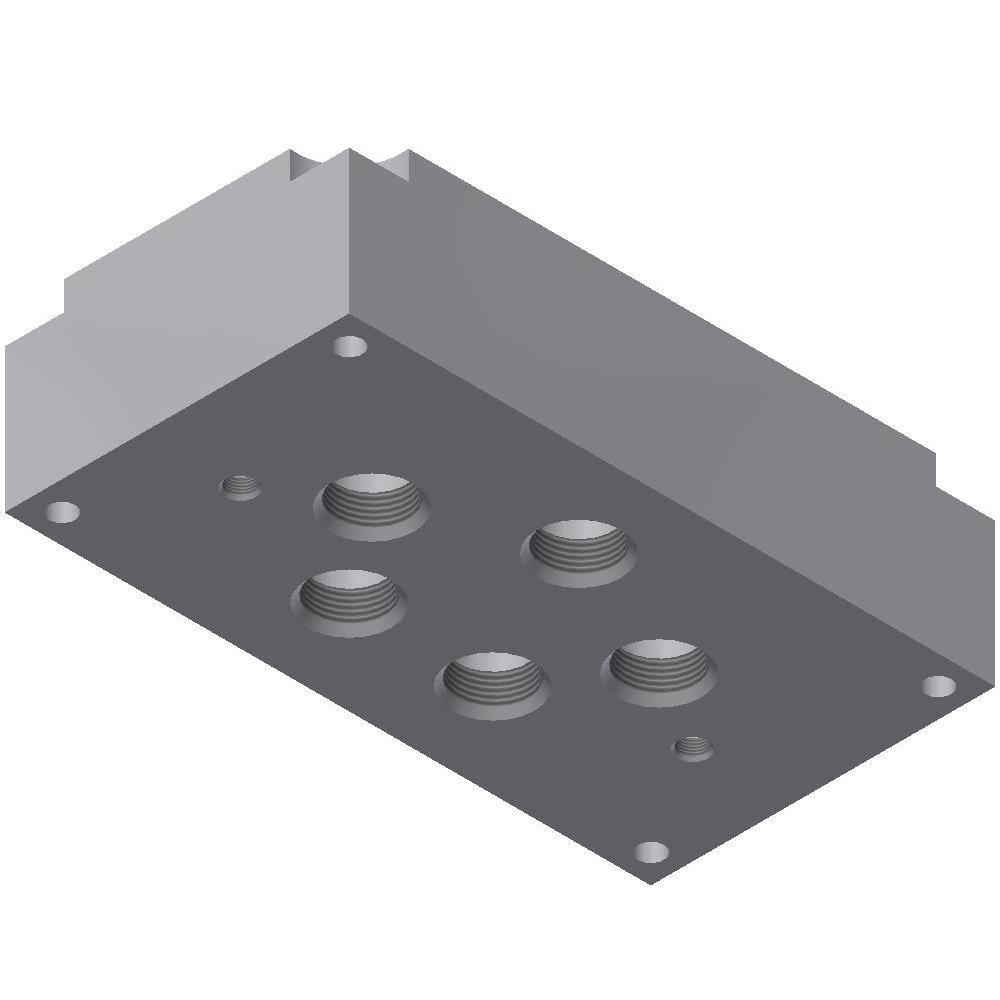
Subplates for 8P Valves - 3/4" Ports
Subplates for 8P Valves - 3/4" Ports with Pilot
Subplates for 16P Valves - 1-1/2" Ports
Subplates for 16P Valves - 1-1/2" Ports with Pilot
Subplates for 16P Valves - 2" Ports
Subplates for 16P Valves - 2" Ports with Pilot


