
7114 Harry Hines Blvd.
Dallas, Texas 75235
214-357-3851
Jiffy Drill

What is a Jiffy-Drill
Jiffy-Drill is the light, powerful, and compact answer to production drilling, reaming, spot facing, and similar operations. It will drill holes up through 1-1/2" diameter in steel with ample allowance for dull bits. In tests, it has drilled 1-3/4" diameter holes in cast iron, and has produced 0.025 chips in mild steel using a Model B-6 hydraulic motor. Using a hydraulic motor to rotate the spindle, the standard unit will produce more than 10 HP, yet is so compact that two units will mount side-by-side on 3-5/16" spacing, or as close as 3-3/16" if hydraulic motor housing is specially machined and if one unit is ordered with feed piston ports on the opposite side, or bottom.
The Jiffy-Drill is very compact when using a hydraulic motor. With a maximum length of less than 27" from end of motor to end of drill chuck when a standard Model B-3 hydraulic motor and a #3 Morse female taper spindle are used. The length is slightly greater with larger hydraulic motors.
View our Drill Product Selector
Jiffy-Drill Stroke
The stroke of the standard Jiffy-Drill unit is 3-1/2". The Jiffy-Drill operates by an SAE 6-spline sliding torque transfer joint. This allows the transfer of horsepower from the stationary drive unit to the linearly advancing spindle. At rest, the drive shaft is retracted into this splined fitting and has maximum spline engagement. As the spindle is advanced forward, this engagement is reduced. As the amount of spline engagement is reduced, the amount of torque that can be transferred to the spline is also reduced. Excessive spline wear should not occur with the following recommended stroke limitation. For torques greater than 350 in.-lbs. use the following limitation on stroke: Stroke (in.) = 3.50 - Torque (in.-lbs.) / 850.
How a Jiffy-Drill Works
Spindle Rotation: The spindle is rotated by your choice of drive style options. We recommend using compact hydraulic motors for greater power. Although in many applications alternative methods to rotate the spindle may be beneficial. Spindle should be limited to 5000 RPM maximum to prevent over heating of the spindle bearing causing possible damage.
Spindle Advance: The spindle is advanced and retracted by a built-in coaxial piston which is powered by hydraulic power. The pressure to advance the spindle is dependent upon the size of the drill. The limit on feed pressure is 800 PSI maximum which will develop over 2500 lbs. thrust. (extend area: 3.14 sq.in., retract area: 1.37 sq.in.)
Position Switches: Built-in electric limit switches (part number J-318) and
cams are used to provide spindle location feedback to your
control circuit. The use of these switches is entirely dependent
upon your control circuit and how you choose to operate
the Jiffy-Drill unit.
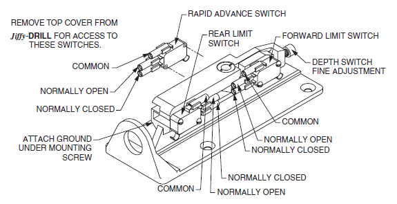
Both the rear limit switch and the rapid advance switch
are securely mounted to the switch plate and sensor trigger
adjustments are easily made by moving the appropriate position
cam. Only the forward limit switch has both a position
cam adjustment as well as a fine adjustment for controlling
stroke limitation.
General Information
The Jiffy-Drill is designed specifically to drill both small holes and large holes in a variety of materials. The size of hole and the material determines the power and RPM required to perform the task. On most applications a single motor is not capable of doing a wide range of holes or materials. In these cases, the motor can be changed to achieve the best power and RPM needed. Although, you can normally sacrifice drilling cycle times to reduce the number of different motor sizes needed.
Mounting the Jiffy-Drill
The unit can be mounted in any position, but if mounted to drill upward, a chip cover should be used to keep coolant and chips out of the electrical switch compartment or use coolant resistant limit switches. There are four, 1/2"-13, tapped holes in the base of the Jiffy-Drill body which can be used for mounting. Caution! The two front mounting bolts must not penetrate more than 1/2" to avoid damage to the feed piston barrel. Although, on most tapping jobs, usually less than 50 lbs. feed force is required, on drilling applications the structure supporting the Jiffy-Drill may have to take up to 2500 lbs. thrust.
When using the Jiffy-Drill unit, we always recommend using a fixed hardened bushing. The design of the Jiffy-Drill allows for smooth extension and retraction, using soft seals and wear rings. The unit can not sustain accuracy if the drill bit is subjected to a side load or drilling on a curved or uneven surface without a hardened bushing. We recommend installing a bushing in a fixture as close to the part as possible. In some cases this fixture and the Jiffy-Drill can be mounted on a slide and becomes an integral part of clamping the part to be drilled.
Hydraulic Setup
A hydraulic power unit to operate a Jiffy-Drill is not part of the Jiffy-Drill but may be ordered as auxiliary equipment, or perhaps a standard hydraulic power unit already on hand can be used. Hydraulic hoses should be ordered locally after the distance between the power unit and the drilling unit is established. Several Jiffy-Drill units, which are powered with hydraulic motors can be run from one hydraulic power supply.
Hydraulic to Rotate Spindle
Flow for spindle motor will be determined by desired RPM on each Jiffy-Drill. Several power arrangements may be used: two (or more) pumps driven from the same or from opposite ends of a double shaft electric motor; a two-section (or more) hydraulic pump; two (or more) separate hydraulic power units. A pressure compensated pump may be used for both the main motor drive and the spindle advance. Spindle rotation is determined by which port is connected to the hydraulic pump. During setup, verify tool rotation.
Choose a hydraulic motor from these tables that will deliver the required torque and RPM. If you will be using an existing power unit, you will be limited by the pressure and flow available from your existing power unit. On new applications try to keep operating pressures around 600 - 800 PSI and GPM at 25% to 75% of maximum GPM the motor can operate at.
On jobs where several Jiffy-Drill units are to be used, one large power unit can serve all the units by having one or more large pumps and with pressure compensated flow control valves installed in each Jiffy-Drill motor circuit and feed circuit.
Hydraulic to Advance Jiffy-Drill Spindle
A flow of 2 GPM is usually sufficient for piston advancement. Hydraulic pressure of 100-800 PSI is needed to advance and retract the spindle when drilling holes. A hydraulic pressure of 200 PSI, for example, working on the internal piston area of 3.14 square inches, will give a thrust of about 600 lbs. on the drill bit. With hydraulic feed pressure up to a maximum of 800 PSI, a thrust of about 2500 lbs. can be produced. It is important to use a pressure reducer and gauge in the feed circuit. (extend area: 3.14 sq.in., retract area: 1.37 sq.in.)
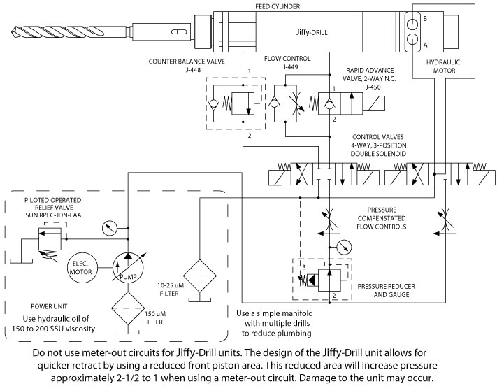
To maximize drill feed control, a counter balance valve should be installed in the outgoing flow line of the Jiffy-Drill. This valve tends to hold the drill back when it strokes forward by resisting sudden high surges in the flow. It should be adjusted to the minimum setting which gives adequate control, as it places an extra load on the hydraulic power source. The counter balance valve should contain a check valve for free flow on drill retraction.
The system compensator setting should not be used to regulate chip thickness. It should be set and locked at a pressure high enough to take care of moderately dull drills, but no higher than necessary because surplus oil from the hydraulic power supply must discharge across it. The higher its setting, the greater the heat generated in the oil.
The 2-way solenoid valve is optional, and used only when a rapid advance up to the work is desired. It should be energized for rapid advance, then de-energized just before the drill bit touches the work. It may be wired to operate from the deceleration switch located on the Jiffy-Drill unit.
Recommended Jiffy-Drill Hydraulic Circuit
Electric Control of the Jiffy-Drill
Three built-in limit switches (part number J-318) should provide adequate switching for design of circuits for fast forward, skip feed, normal feed, dwell, reverse, and reverse stop. Each switch is actuated by an adjustable cam. The forward limit switch has a fine thread adjustment for drill depth. After setting its cam for approximate depth, loosen lock screw and adjust screw for fine adjustment. Turn adjusting screw clockwise for a depth increase of 0.0357" per turn. Tighten lock screw to secure adjustment screw.
Limit switches are rated up to 4 amps at 125 volts A-C or 1/2 amp at 125 volts D-C. Use relays, if necessary, to control higher current or voltage.
On standard Jiffy-Drill units these switches are not wired, and the external wiring is brought through the conduit hole in the rear of the switch cover. For factory wired units see option EP.
Sample Electric Circuit Operations
The following samples only consider the electrical controls needed to control the extension and retraction of the feed cylinder for various types of drilling operations. The control of the spindle rotation may be incorporated into the feed circuit. Although for most applications the spindle rotation control is independent of the feed. These circuits serve only as a guideline in assisting you in setting up the Jiffy-Drill. We currently use several of these circuits in our manufacturing facility, but caution is urged to limit possible damage during the initial setup and testing of your control circuit. In some cases, customers have incorporated a reverse spindle rotation option during the initial design of their machining center.
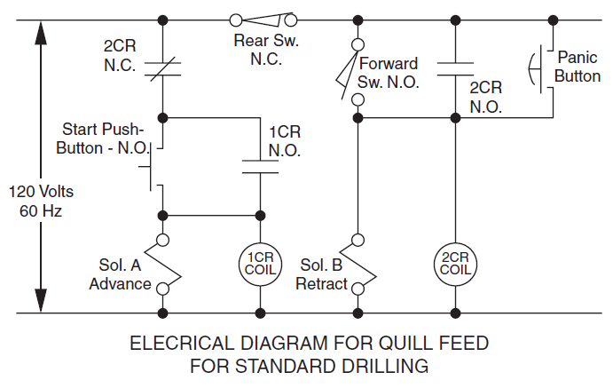
Standard Drilling
Hole Reaming
Spot Facing
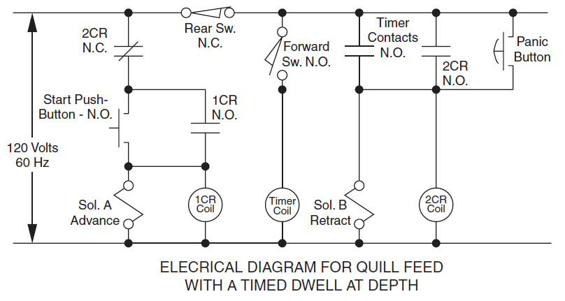
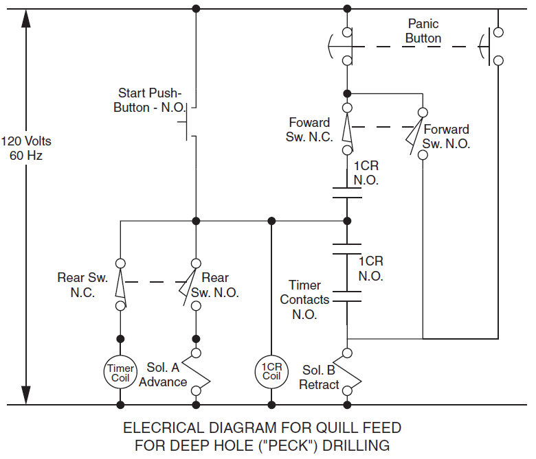
Peck Drilling
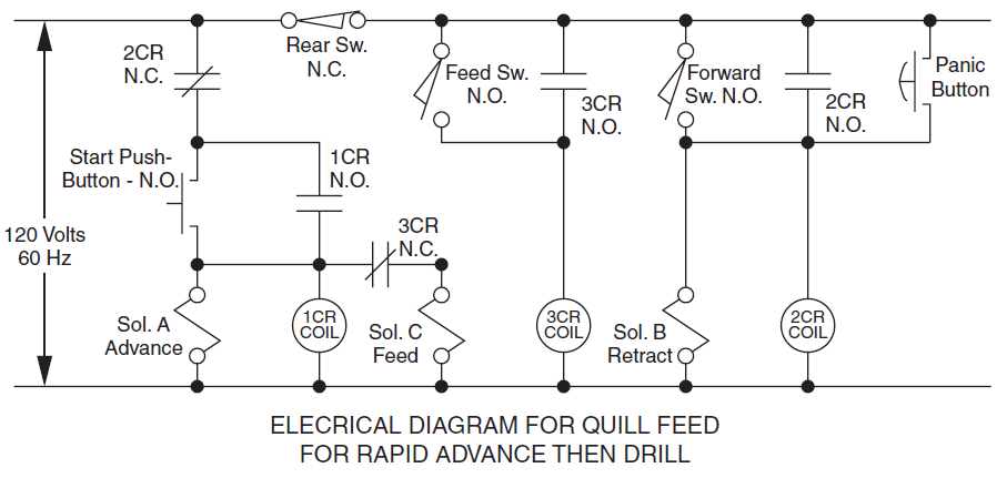
Rapid Advance Spindle, Then Slow Feed Drill
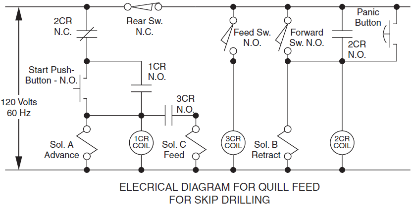
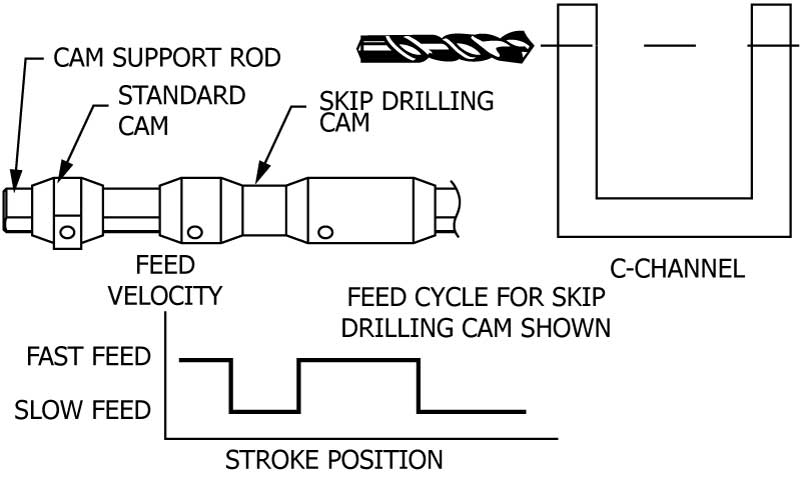
Skip Drilling
Parts Drawings and Information
For parts and dimensional drawings please use the Product Selector to get information about your specific model.
Routine Maintenance Items
Spline Drive Lubrication: The spindle drive spline
should be wiped generously with a high film strength grease.
To reach the spline, unscrew the bearing retainer. This is a
left-hand thread. Pull out the spindle for access to the spline.
Wipe a light film of the same grease on the switch cam
rods where they go through the torque plate.
Hydraulic Drive Motor: This motor is lubricated by the hydraulic oil and needs no other lubrication. Should the shaft seal ever need replacing, seal kits are available, complete with instructions.
Removing Drill Bits: With Morse taper spindles, drill bits should be removed from the spindle by inserting a lever-type drill knock-out in the slot provided. Caution! Do not hammer on the knock-out or spindle; this may damage the spindle bearing.
Quill: Keep dirt wiped off the quill, and lubricate it once every 12,000 cycles or once a month, whichever is sooner, with a few drops of oil.
Limit Switches: Routinely inspect limit switches for loose contacts, damaged trigger levers, broken or worn mechanisms, and general structural rigidity.
Seals: Visually inspect unit for hydraulic leakage which could indicate the need for seal replacement. (Seal leakage is a very rare occurrence.)
Removing Spindle Bearing
First remove spindle as described under spline drive lubrication. The spindle and drive shaft are locked together by a tapered pin. Punch the taper pin out by striking it from the side labeled X-X. To remove the bearing, the two parts of the spindle must be unscrewed from each other. These are standard right hand threads.
Interchanging Hydraulic Motors
In setting up for a different job, the hydraulic motor can be interchanged with a different model which may have a more favorable ratio of torque and RPM for the new job. See our motor quick change option on page 12 for alternative options.
Remove four socket head nuts. Pull out the motor with spline sleeve still attached. The spline sleeve set screws are swedged in place and removal might be difficult. It is recommended when using interchangeable motors, that you keep the spline sleeve attached and not swap sleeves between motors. If removal of sleeve is necessary, the swedge must be removed by deburring or use a small end mill to remove swedge. Loosen set screw, and pull spline sleeve off motor shaft. Transfer motor ring, if used, to new motor shaft. Replace spindle sleeve and re-swedge tightened set screw. Unscrew four studs from the old motor and mount them on the new motor. Place the spline sleeve on new motor shaft and tighten set screw. Plug the new motor assembly into the Jiffy-Drill body, engaging the spline sleeve with the spline on the spindle. Reinstall and tighten the four socket head cap nuts.
Recommended Spare Parts
At least one spare limit switch (part number J-318) should be kept on hand. In an emergency, the deceleration limit switch, if not used, can be substituted as a replacement for one of the other switches.
When replacing a limit switch, transfer one wire at a time from the old to the new switch, to avoid the possibility of getting the new switch wired incorrectly.
Locating Unit Serial Number
The unit serial number is located on the right side of the unit when looking at the spindle end. Be aware that the covers between units are interchangeable. Therefore, the part number on the cover may not be the correct part number of the unit. Consult the factory for determining the exact part number of your unit or locating the serial number. Serial number may be required when ordering replacement parts.
Seal Kits
Seal kits are available from your local distributor or the factory. Be prepared to supply unit serial number to determine proper seal kit number.
- RKJD-1: Complete soft seal kit for serial numbers up to 577Ql. (Units purchased prior March, 1986.)
- RKJD-2: Complete soft seal kit for serial numbers starting with 578Q3.
Drill Cylinder Seal Kit Installation
- Remove bearing retainer nut (left hand thread). Pull drive shaft out.
- If there is an adapter ring, remove by first removing the two loc-tited set screws in face. Use a torch to break the loc-tite bond. Remove the adapter ring (left hand thread).
- To remove stop rod mounting plate, loosen socket head cap screw at bottom. Use a flat head screw driver to slightly spread stop rod mounting plate and slide mounting plate off of the quill. You will need to remove the switch cams to completely remove stop rod mounting assembly.
- To remove torque plate, remove 4 mounting screws. Pull torque plate up to the threads on quill. It is easier to remove plate by unscrewing seal around thread (left hand thread).
- To remove cylinder rod end, rotate rod end 45 degrees, slide off rod end using the corners to grab hold of. Remove bronze bearing and seal from the rod end. Remove quill from the barrel. Remove seals, being careful not to damage quill surface. Clean and dry surface of all parts before re-assembly. Lubricate using high film strength grease.
- Replace seals using a small screw driver, being careful not to damage seal or quill surface. Using a thin film of grease on the seals will improve installation and sealing.
- Re-assemble in reverse order.