

Handy-Thread
What is a Handy-Thread
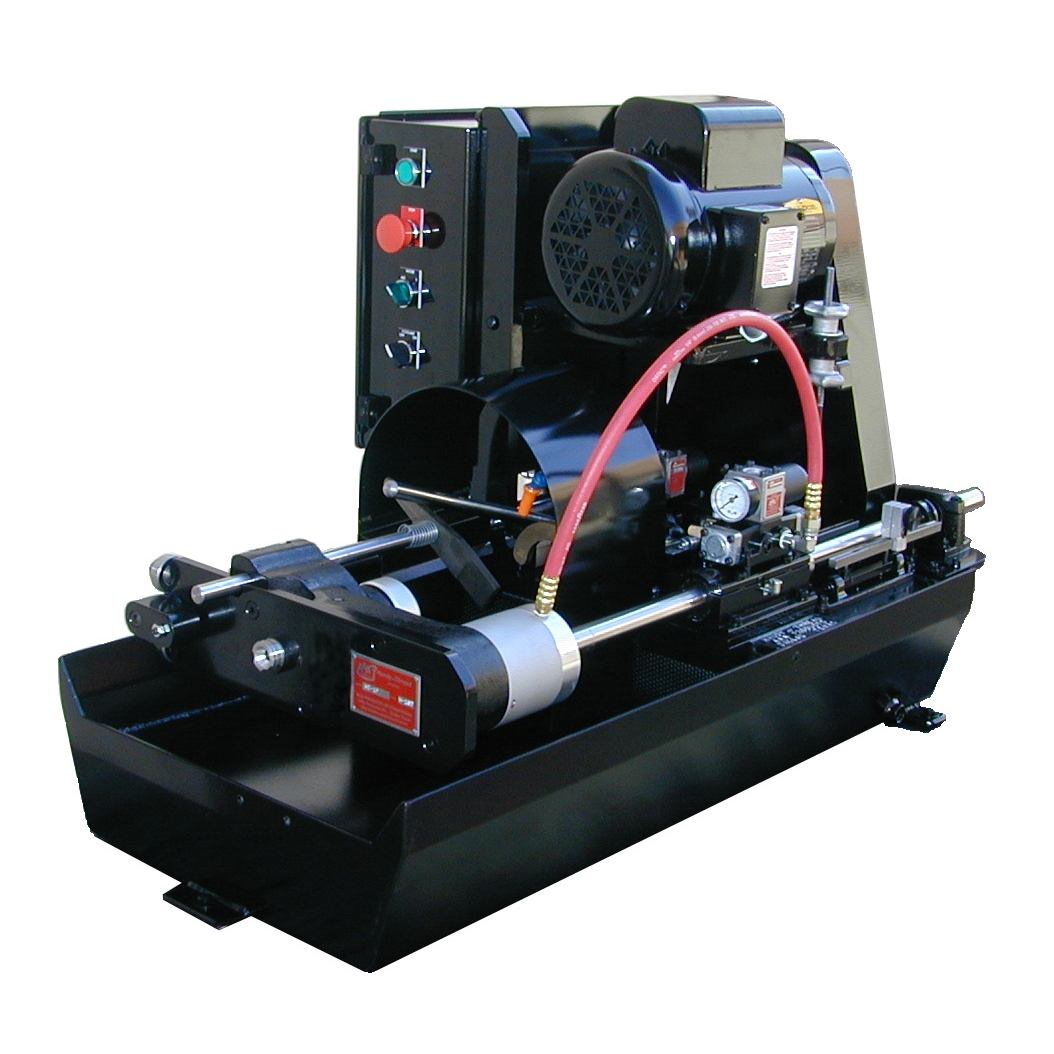
"Handy-Thread" is a quality, high production rod threading machine that is easy on the budget. It is a compact machine designed for continuous duty, high production threading of rods from 3/32" through 5/8" diameter. Approximate size: 24" x 39" x 27" high. Weighs less than 300 lbs. It can be moved easily to the job mounted on a rolling table or bench. Plug it into a standard 120-volt, 3-prong electrical outlet, connect it to the shop air supply, and it is ready to go to work. The machine can be operated with one hand. The carriage, mounted on ball bearings, rolls so easily that there is little operator fatigue. There are no foot switches to stumble over and even an unskilled operator can immediately learn to operate it with no special training. Thread quality will be as good as your threading head is capable of making. The quality of your thread is limited only by the quality of your threading head.
How it works
The patented "Handy-Thread" machine operates on a completely different principle than other threading machines on the market. It has no chucking or feed levers, no foot switches, and no clutches. All that is required of the operator is to insert the rod to be threaded through a short collet and against a stop, push the rod and carriage slightly forward (the chuck clamps the rod and the stop swings away), continue pushing the rod and its carriage forward until the rod engages the rotating threading head. At the proper thread length the threading head opens automatically. The operator then pulls the carriage (and rod) back to full retracted position and withdraws the threaded rod. Clamping and unclamping of the rod in its collet, and opening and re-cocking of the threading head are all done automatically as the movement of the carriage actuates various adjustable limit switches.
The machine can quickly be set up for different threads. The operator removes the collet and threading head then installs the new collet and threading head and sets the desired thread length, using the built-in calibrated thread length quick set gauge. The machine is then ready for operation. It will produce any thread in its size range as fast as it is possible to run the threading head without damage to the head, or without exceeding the HP rating of the electric motor. A larger electric motor can be furnished to order.
Handy Thread Video
Features of the Standard No. 1 Model
This is a non-reversing machine which will handle the majority of rod threading jobs. All concepts used in the "Handy-Thread" are practical, proven technology.
The standard model uses a 1-1/2 HP, 120-volt, 1725 RPM single-phase electric motor. As assembled at the factory it produces a spindle speed of 400 RPM which is satisfactory for most jobs. However, a different set of pulleys will be installed at the factory before shipment when requested, or the pulleys and cog belt can readily be changed in the field for faster or slower spindle speed.
Since the motor never reverses during a threading operation, and never stops between threading operations, the motor will not overheat when the machine is used within the specified range of rod diameter, type of material and horse power.
Rod Diameter
This model will thread the equivalent of mild (cold rolled) steel in diameters up to
5/8".
For rods of larger diameter or harder material a model with a larger electric motor
is
recommended.
Rod Material
Most materials for which the threading head is suited can be threaded, HP being the
limiting
factor.
Thread Length
This model will produce threads up to 6" long, and can thread to within 1/2" of the
end of a
rod (a minimum of 1/2" is required for the collet to grip the rod). Rods as short as
1" long
can be threaded. Longer threads or continuous threading of long rods also can be
done on a
standard machine using continuous thread mode.
Alternate Threading
All models of the "Handy-Thread" have the Alternate Threading feature. Two thread
length
limit cams are provided which can be set to different thread lengths. The operator
can cut
threads to different lengths on opposite ends of the same rod, up to 3-1/2" long on
one end
and up to 6" long on the opposite end. The first threads one end, then inserts the
opposite
end for a different thread length. After initially setting the two length stops the
alternate threading operation is automatic. When the alternate threading feature is
turned
off, the machine will cut the same length on each end up to 6" long.
Threading Heads
The "Handy-Thread" machine can be ordered to use almost any brand of 5/8" capacity
rotating
head. The threading head must be the quick-opening, rotating type which has
provisions for a
yoke to open and close the head. Purchase heads from your local machinery house or
contact
factory. The machine must be fitted at the factory for the particular brand
threading head
which you will use.
The "Handy-Thread" machine can be adjusted for accurate thread lengths, and will repeat to an accuracy of plus or minus 0.015" . The collet can be centered on the threading head with sufficient accuracy to produce any class thread of which the head is capable. Thread lead is held very accurate because of the low friction, free traveling ball bearings on which the rod chuck carriage travels.
U-Bolt Threading
U-bolts having a throat as small as 2" and a minimum overall length of 7" can be
threaded
even after the U-bolt has been bent.
Power Requirements
A standard "Handy-Thread" machine with 1-1/2 HP electric motor operates from 120
volts,
single phase, 60 Hz, with 20 ampere draw (on 120 volts). A power cord with a 3-prong
grounded plug which fits a standard 20-ampere 3-prong receptacle is furnished. A
source of
85 PSI shop air is also required for operation of the collet and threading head
closing
cylinders. If shop air is not available, a small compressor of 1/2 HP which will
deliver at
least 85 PSI can be used.
Equipment Furnished
All single-phase "Handy-Thread" machines are furnished complete with 120- volt, 60
Hz motor;
power cord and plug; electric control box; pressure regulator for the compressed air
line;
coolant pump; drive belt and two pulleys; and 5 sizes of rod guide bushings.
Collets, threading head are not furnished unless specified on your order. The machine will accept spring-type, No. 11 Hardinge or B & S collets. They can be included with your machine order or can be purchased locally from your machinery dealer.
Special collets to hold square or hex rods can be ordered with your "Handy-Thread" machine or can be obtained from your local machinery dealer. Special size collets for thread rolling are also available (for under size thread rolling rod).
Special Electric Motors
For threading rods 5/8" diameter, or material harder than mild steel, a slower
spindle speed
with greater torque will be needed. For these applications the machine can be
ordered with 2
HP, 1725 RPM, 120/230-volt, 60 Hz, single-phase electric motor. The pulleys normally
furnished with this motor give a spindle speed of 400 RPM. This larger motor and
various
pulley combinations to give spindle speeds in the range of 400 to 1700 RPM can be
furnished
on original order or can be installed in the field on existing "Handy-Thread"
machines.
Construction
The "Handy-Thread" machine requires very little maintenance because all moving parts
in the
clamp cylinder and collet chuck are solid bronze or chrome plated to prevent rust
from water
base cutting fluids. The chuck body is made from alloy bronze and requires very
little
attention. All solenoid valves are controlled by a PLC.
The traveling carriage on the "Handy-Thread" machine is all sealed ball bearing running on hard rods, and the work can be fed into the threading head with little effort.
The CNC machined base plate is made from a single heavy aluminum alloy casting, and is mounted to the cutting fluid tank with a 3-point mount to prevent distortion if the cutting fluid tank is bolted to an uneven surface.
This machine, in production for over 18 years, is truly a fine piece of production equipment, built by a company with over 40 years experience in special machine manufacturing and used in production by many major manufactures. Contact us for a list of satisfied owners.
Geometric, Acme-Fette, H & G, Vers-O-Tool
Landis Solutions LLC
360 South Church Street
Waynesboro, PA 17268
Phone: 800-358-3500
Fax: 888-718-2922
1"KD
DR3/8
DR9/16
9/16KD
TDR5/8
DR13/16
DRF13/16
MMC101
NY1
NY2
Landis Threading Systems
Landis Threading Solutions LLC
360 South Church Street
Waynesboro, PA 17268
Phone: 800-358-3500
Fax: 888-718-2922
Web:
http://landis-solutions.com
1/2 4JN
13/16 13JN
3-1/2TRRB
5TRRB
7TRRB
LMT-Fette
LMT USA, Inc.
1081 S. Northpoint Blvd
Waukegan, IL 60085
Phone: 800-757-0346
Web: www.lmtfettetools.com
None
K1Y
K2Y
Reed Machinery, Inc.
Reed Machinery, Inc.
10A New Bond St
Worcester, MA 01606
Phone: 508-595-9090
Fax: 508-595-0002
Web: www.reed-machinery.com/
None
#510ERR (Obs / Parts only)
RSVP Tooling
RSVP Tooling
227 Airport Drive
Joliet, IL 60431
Phone: 888-289-7787
Web: www.rsvptooling.com
DR-3/8
DR-9/16
DR-13/16
RK1
RK2
Thread Sizes
The Handy-Thread machine is ruggedly constructed, and fully adjustable in every way. The standard machine will cut or roll threads from 1/8" through 5/8" N.C., N.F., or 16mm with the proper heads.
Electrical Requirements
The standard non-reversing machine uses a 1-1/2 HP, 1725 RPM, 115 volt, 60 Hz, single-phase electric motor with 3-prong grounded plug. It should be plugged into a 3 prong grounded receptacle with 20-ampere capacity on 115 volts.
Compressed Air Supply
The standard machine requires a compressed air supply of 85 PSI minimum gauge pressure, with a flow capacity of about 1/2 SCFM (standard cubic feet per minute). If no compressed air is available in the plant, or a stand alone unit is desired, a small air compressor of 1/2 HP which will deliver at least 85 PSI should be adequate for most jobs. The compressor should be used with a receiver (storage tank) of 10 to 30 gallons capacity.
Cutting Fluid or Coolant
Modern chemistry is developing many new and improved cutting fluids. Contact your local supplier of cutting tools if you have no special source for purchasing cutting fluid. The fluid should have a viscosity of no higher than 200 SSU (rated at 100°F). A minimum of 5 quarts and a maximum of 8 quarts is required in the Handy-Thread reservoir. When filling the reservoir, pour the fluid into the chip pan. It will drain through the chip screen into the reservoir.
Caution! Do not mix cutting fluids of different kinds because of the possibility of forming gums which will clog the pump, the coolant tube, or die head.
If the fluid discharge tube should become clogged it can usually be cleared with a blow gun without removing it from the machine. Blow backward through the tube. If necessary to remove it for cleaning, unscrew the pipe where it comes out of the machine base plate and pull the tube out.
Caution! Running the pump without cutting fluid may damage it. If fluid is not desired for threading certain materials, turn the pump off with the selector switch on the electric control box.
If the cutting fluid is too thick (viscosity too high), the pump may have difficulty in picking it up when the machine is first started and the fluid is cold. This may happen even with thinner fluids in cold weather.
Caution! Do not use flammable or aromatic solvents to thin the cutting fluid because of the danger of fire.
Remove/Install Die Head
To install or remove a complete die head, remove cutting fluid guard and loosen (about 2 turns) the socket set screw(s) in the spindle behind the die head. Move the die yoke latch bar to the right and lift the bronze die yoke out of its groove in the die head. The die head is now ready to be removed by pulling it toward the operator. Do not hammer on the die head if it is tight; drive a thin wedge or screwdriver between the die head and the spindle.
Some die heads have die blocks which can easily be removed while the die head remains in the machine. This allows a quick change of thread size or thread lead. Consult the instruction manual for your particular brand of die head and proceed accordingly.
To re-install the die head, slip the shank into the spindle hole. Be sure the flat on the die head shank is exactly in the center under the spindle set screw(s). Tap the die head lightly with a soft hammer until its base seats against the end of the spindle, then tighten the remaining set screw(s) in the spindle, drop the die yoke into its slot, pull the yoke latch bar to the left, and re-mount the cutting fluid guard. Next, select the proper size rod guide bushing which mounts on the carriage plate and twist 1/8th turn clockwise. The rod guide bushings are about 1/32" larger than the diameter of the rod to be threaded.
Next, unscrew the collet retaining nut on the air chuck and remove the collet. Install a collet for the size rod to be threaded, re-assemble the collet retaining nut, and tighten.
Cutting Single Threads
For threading only one end of a rod, or for threading the same length on opposite ends of the same rod, first make sure there is at least 85 PSI air pressure showing on the gauge. If pressure is low, raise it with the pressure regulator located beneath the electrical control box. Turn the "Alt-Cont-#1" selector switch to its No. 1 (right) position. The indicator light located inside the selector switch should light. Set the right switch cam (the one on the longer switch bar) to the desired thread length by reading the scale at the front (operator) end of the switch bar. Tighten the knurled cam knob finger tight. If threading a material which requires cutting fluid or coolant, turn on the pump selector switch and wait until fluid begins to flow. Adjust the position of the fluid tube to direct the full stream of fluid onto the rod just before it enters the die.
Insert the rod to be threaded through the rod guide bushing and collet, stopping it against the swing stop arm. Gently push the carriage toward the die head. Do not bump the rod into the die head because it may chip the chasers.
After engaging the rod into the die head about 1/8", the rod will be pulled along by the die until the switch cam is contacted, at which time the die head will be automatically opened by the die head air cylinder.
Caution! Do not start to thread unless there is at least 85 PSI air pressure. The gauge is mounted on the collet air valve. Without sufficient air pressure the collet will not clamp the rod securely, and the die head will not open when the switch cam is actuated. If, after starting to thread, you discover the air pressure to be less than 85 PSI, turn off the electric motor as quickly as possible to prevent the collet from jamming into the die head. Use the "Stop" push button on the control box.
Note: For threading rods which are shorter than about 7" long, the rods must be inserted into the collet from the opposite side. In this case the rod guide bushings and the swing stop assembly are not used. The accessory twist-on stop rod assembly (furnished with each Handy-Thread machine) is inserted in place of the rod guide bushing, and adjusted to provide a stop of the proper depth as the rod is inserted into the collet. Rods as short as 1" long can be threaded in this way. The swing stop assembly may be left in place while threading short rods, or if a large number of short rods are to be threaded, the complete swing stop assembly can be taken off by loosening the two socket head screws on the top of the stop rod bracket.
In using the accessory twist-on rod stop assembly, the measuring rules on the switch bar will not be usable. A trial cut will have to be made, and if the thread length is too short, the switch cam will have to be re-set for a slightly longer thread. After a little experience the correct length will be produced on the first or second trial.
Alternate Threading
Alternate threading is the cutting of threads on opposite ends of the same rod to different lengths. The machine can be set to alternately produce a shorter, then a longer thread. The operator can thread a rod on one end then withdraw it and re-insert the opposite end for a different length thread. To set the Handy-Thread machine for alternate threading, first turn the "Alt-Cont-#1" selector switch to its "Alt" (left) position. The indicator light will light only on every other carriage stroke. When it lights, the next thread length will be that set on the right switch bar cam, usually the longer thread length. Next, set the left switch bar cam for the shorter and the right switch bar cam for the longer thread length. As the machine comes from the factory, the shorter switch bar cam can be set for up to 3-1/2" and the right switch bar cam for up to 6" thread length.
Continuous Threading
Continuous threading is the cutting of threads longer than 6". To set the Handy-Thread machine for continuous threading, first turn the "Alt-Cont-#1" selector switch to its "Cont." (middle) position. During this mode only the right switch bar cam is active. When the length set on the right switch bar is reached the chuck is opened and the head remains closed. Caution: at this time the rod will spin, so provisions must be made to insure operator safety. When the carriage is returned to the neutral (back) position, the chuck will close on the part and allow an additional length of rod to be threaded. Continue to cycle the length of the rod you wish threaded. Just prior the last cycle of the desired threaded length, switch the "Alt-Cont-#1" switch to "#1" (left) position. When the right switch bar is reached this time, the head will open. Turn off the machine to stop the rotation of the head and to release the rod from the chuck. It is important to turn off the machine prior returning the carriage the neutral position to prevent damage to the threads. To determine the setting for the right switch bar, divide the length of the desired thread in to even cycles less than 6" (ie. to cut a 15.75" thread, set the switch bar to 5.25" and run for 3 cycles).
Handy-Thread Accessories
Standard accessories furnished with the Handy-Thread machine include five sizes of quick-change rod guide bushings, each with a hole slightly larger than the rod to be threaded. These bushings are for supporting the rod and guiding it into the collet. Also included is the accessory rod stop for use in threading very short rods. This stop is used in place of the swing stop for short rods, and twists on to the carriage plate.
The standard machine uses standard No. 11 collets. These are not furnished unless specified on your order. Round collets in increments of 1/64" in diameter from 1/8" through 13/16" are available from AAA Products. Larger rods, up to 1" in diameter, can be held by using an optional special collet sleeve, collet retaining nut, and using a standard No. 21 collet. For information contact the Jiffy Products Division of AAA Products International. Special collets to hold hex and square rods are also available from the factory.
Threading Speeds
The kind of material, its hardness, and its diameter will determine the maximum spindle RPM which can be used. The standard machine is assembled with motor and spindle pulleys to have a speed of 400 RPM on the spindle. This is a good speed for a wide range of threading jobs, for cold rolled (low carbon) steel up to 1/2" in diameter with the right cutting fluid. Larger rods of this material can usually be threaded at this speed although die chaser life may be reduced. However, on long production runs, spindle speed should be reduced on rods larger than 1/2" in diameter. It is quite important that the proper amount of the right cutting fluid be used and that it be directed on the rod as close as possible to the place where the material enters the die.
If rods of less than 3/8" diameter are to be threaded in quantity, the spindle speed can be increased by replacing the motor pulley with one of larger diameter. We recommend your die manufacturer be consulted for best surface speed of a particular material along with recommendations on lubricant or coolant.
For threading harder materials such as stainless steel or higher carbon steel, the spindle should be run at a slower speed. The standard pulley supplied on standard units may be replaced with an optional pulley. These are standard timing belt pulleys for a 1" wide belt, and can be purchased either from the factory or from a local power transmission dealer. It is unimportant to change the pulleys for a short run of small rods.
For best production rate the machine should be run, if possible, at the highest RPM or surface speed (SFM) recommended by the head manufacturer. When running at higher speeds, particularly on large diameter rods, or when threading harder materials, it is especially important to use the right amount of the right cutting fluid and to see that it is directed properly.
Changing Belt and/or Pulley
Remove the drive belt guard and loosen the belt tension adjusting knobs. Remove the belt and the motor pulley. Install the replacement pulley. Align the motor and spindle pulleys, then tighten the pulley screws. Install the belt, then adjust the belt tension knobs to produce a light tension on the belt. Install the belt guard. Caution! Do not operate the machine without the belt guard in place.
Yearly Maintenance
The cutting fluid reservoir should be cleaned about once a year for normal use. For access to the reservoir, remove the three 3/8" socket head cap screws and one flat head screw in the side of the pan which hold the machine base plate to the pan. It will be necessary to remove the belt guard for access to the two screws in the rear. Since all parts are attached to the base plate, the entire assembly can be lifted clear when the four screws are removed.
Caution! When re-installing the base plate assembly, be sure the washers between the base plate and the pan are in place. These washers give the base plate a 3-point suspension so any movement or twisting of the pan will not cause machine mis-alignment.
The spindle head bearings should be greased at least once a year of normal use. Use a good grade of bearing grease and apply it sparingly.
Lubricate in the air line by disconnecting it at the regulator outlet and squirting in a small amount of light machine oil - no more than 20 drops - then re-connecting the line. Do not put oil in the regulator.
Monthly Maintenance
Lubricate the ball bushing blocks and yoke slide which are located on the right side of the machine, by squirting in a small amount of light maching oil - no more than 20 drops.
Wipe a few drops of oil on the under side of the stop cam rod and on the carriage support rod on the left side when facing the machine. Put a drop of oil on the swing stop hinge bolt, and a drop on the switch bars behind the ball bushing block. Wipe the switch cam bars with a slightly oily rag. Put one drop of oil on each 60° hinge at the bottom of the switch bar assembly.
Remove the collet retaining nut and take out the collet. The collet sleeve should then pull out easily. Put a light coat of grease on the collet sleeve, both inside and out, then re-assemble.
Remove the belt guard and check the belt for tension. It should be just tight enough to be snug on the pulleys but not "fiddle-string" tight.
Put a few drops of oil on the bronze die opening yoke and on the latch bar slot and on the 5/8" round die yoke shaft. See your die head instruction manual for die head lubrication.
Handy-Thread Machine Adjustments
The Handy-Thread machine is built for long life and rugged daily use; the die head chasers are the only parts which may have to be replaced on a regular basis. The following simple adjustments may be required occasionally:
Air Pressure
The air line pressure should be adjusted until the air pressure gauge on top of the air
clamp valve reads at least 85 PSI. This adjustment is made on the pressure regulator which
is located under the electric control box. After setting the pressure, cycle the machine
once without cutting threads, to be sure the pressure has stabilized.
Drop Stop
This is set at the factory 6-1/8" from the stop rod mounting bracket. The length of thread
cut when the switch cams are set, can be varied about 1/8" plus or minus by loosening the
two socket head cap head cap screws in the left side of the stop rod mounting bracket, then
sliding the stop rod in or out until thread lengths cut on a test rod correspond to the
length to which the switch cams are set on the switch bar rules.
Switch Bars
Each of the two switch bars can be adjusted to make the thread length longer or shorter by
1/16" each way. This is done by loosening the lock nuts on each end of the switch bars, then
loosening one socket set screw and tightening the other. These 60° socket set screws
should
be set so there is no side movement or end play, but so the switch bar will rock freely;
then tighten the lock nuts and check the movement again.
Die Head Adjustments
Refer to the die head instruction manual for the brand and model of the die head being used.
Note: When using water soluble cutting fluids, all die head models will require periodic disassembly, cleaning, and oiling to remove gum and rust. The need for cleaning will be obvious from the sluggish opening and closing of the die head.
Centering Die Head Horizontally on the Collet
If it should become necessary to re-center the die head on the collet in a horizontal
direction, slightly loosen the four 1/2" hex head bolts which hold the main spindle bearing
blocks to the machine base plate. Tap both bearings to the left or right as required.
The main spindle should measure parallel to the ball bushing rod so that when a straight rod is chucked in the collet it will hit the center of the die head when the carriage is pushed toward the die head. After making this adjustment, firmly tighten the four hex head bolts.
Centering Collet Vertically on the Die Head
Raising or lowering the collet so it will be in alignment with the die head is done with the
two cams (upper and lower) which support the carriage plate. These are located near the
operator, on the left side of the machine.
Recommended adjusting procedure is to take a headless bolt and screw it into the closed die until about 1" of its unthreaded end is protruding out of the die. Disconnect air pressure or unplug the electrical power so the collet will not close. Push the carriage forward and adjust the carriage support cams so the collet will slide freely over the headless bolt. Each cam is adjusted by slightly loosening the socket head cap screw going through its center, then rotating the 5/8" hex cam to the desired position. Tighten the screw while holding the cam to keep it from rotating. When properly adjusted, there should be no up and down play in the carriage.
Replacing an Electrical Limit Switch
There are three limit switches, and any one of them can be replaced by removing the four
1/4" socket head cap screws holding the switch assembly. The switching assembly can then be
moved back and out from under the switch cam collar. Turn the switch assembly on its side to
remove a switch. All switches are Omron switch No. Z-15GD55-B7-K.
When replacing a faulty limit switch, remove only one wire at a time. Connect this wire to the same terminal on the new switch before removing another wire.
The three limit switches can be identified as follows: the one mounted crosswise to the others operates the collet solenoid air valve (the one with a gauge mounted on it) and also re-cocks the die head through the double solenoid air valve. The switch next to it (in the middle) is actuated by the left switch cam bar. When actuated, it opens the die when thread length is reached, but is operative only when the "Alt-Cont-#1" selector switch on the control box is in its "Alt" (left) position for alternately threading to different lengths on opposite ends of the same rod. The third switch also opens the die when actuated. It opens the die on every threading operation when the "Alt-Cont-#1" switch is set in its No. 1 (right) position and on every other threading operation when the "Alt-Cont-#1" switch is set in its "Alt" (left) position.
For helping the operator guide the rod into the collet. All "Handy-Thread" machines are supplied with 5 sizes of rod guide bushings for 1/4", 5/16", 3/8", 1/2", and 5/8" diameter rods. Other sizes may be ordered, but 1/4" is the smallest size. Note: Bushings are bored out to 1/32" greater than nominal rod diameter. Specify rod size when ordering.
For adapting a small diameter threading head shank up to 1" in diameter. Specify shank diameter of your present head.
No collets are furnished unless specified. For thread rolling, collet size must be undersize to fit roll stock rod.
SPECIAL COLLETS for square and hex rods.
Many combinations of horsepower, speeds, voltage, left-hand threads, etc. within the machine limitations are available.
Troubleshooting
The Handy-Thread machine is designed for very simple operation but is constructed ruggedly for long and trouble free operation if the maintenance suggestions in this bulletin are followed. If the machine should ever become inoperative, the following suggestions may prove helpful:
Mechanical Problems:
A visual inspection will usually reveal any problem due to mechanical breakage,
misalignment, loose belt tension, broken belt, etc. If the motor seems to be running
overloaded, check for dull or chipped die chasers.
Compressed Air Problems:
(a). Make sure the pressure gauge shows at least 85 PSI before engaging a rod into the die.
The machine will work at higher pressures up to a recommended 120 PSI maximum. However, the
collet may not securely hold large diameter rods on pressures less than 85 PSI. Adjust the
pressure with the regulator located underneath the electrical control box.
(b). If the air cylinder(s) will not open and/or close the die head or collet, make sure the solenoid valves which control these cylinders are working properly. To make sure the main spool in a solenoid valve is shifting when the solenoid is energized, an air pressure gauge may be teed into the cylinder port on the valve or directly into the cylinder, whichever place is more convenient. If no gauge is available, a port fitting on the valve or cylinder may be slightly loosened to create an air leak at the fitting. Air leakage at a fitting is an indication that air pressure is on it. Replacement seal kits are available for the solenoid valves.
(c). Piston and/or rod seals in the cylinders may eventually have to be replaced. They may be purchased from the factory as complete overhaul kits. Severe internal leakage at the piston seal may affect cylinder performance; its ability to securely clamp the collet on a rod, or ability to open or close the die head. Abnormal piston seal leakage on the die close cylinder will cause air to leak out of the exhaust port(s) of its solenoid control valve during the time the cylinder piston is not moving. On the collet clamp cylinder, if seal is worn out this will be evident by air coming out under the clamp cylinder base, but only when the collet is clamped.
The piston seal can be replaced by first removing the set screw and unscrewing the head off of the clamp cylinder. Important! This is a left hand thread!
Troubleshooting the Electrical Circuit
The electric motor and the coolant pump on the standard Handy-Thread machine operate on 120 or 220 volts, 60 Hz. All other circuits operate on approximately 24 volts D-C obtained from the power supply line through a transformer and rectifier in the control box. The 24 volt circuit is protected with a 1 amp fuse for 220 volt or a 2 amp fuse for 120 volt service. Low voltage operation provides greater safety for the operator or service technician and renders the control circuits less susceptible to short circuiting if accidentally splashed with coolant. D-C operation gives more positive control of solenoid valves, with better switching repeatability.