
7114 Harry Hines Blvd.
Dallas, Texas 75235
214-357-3851
Jiffy Tap
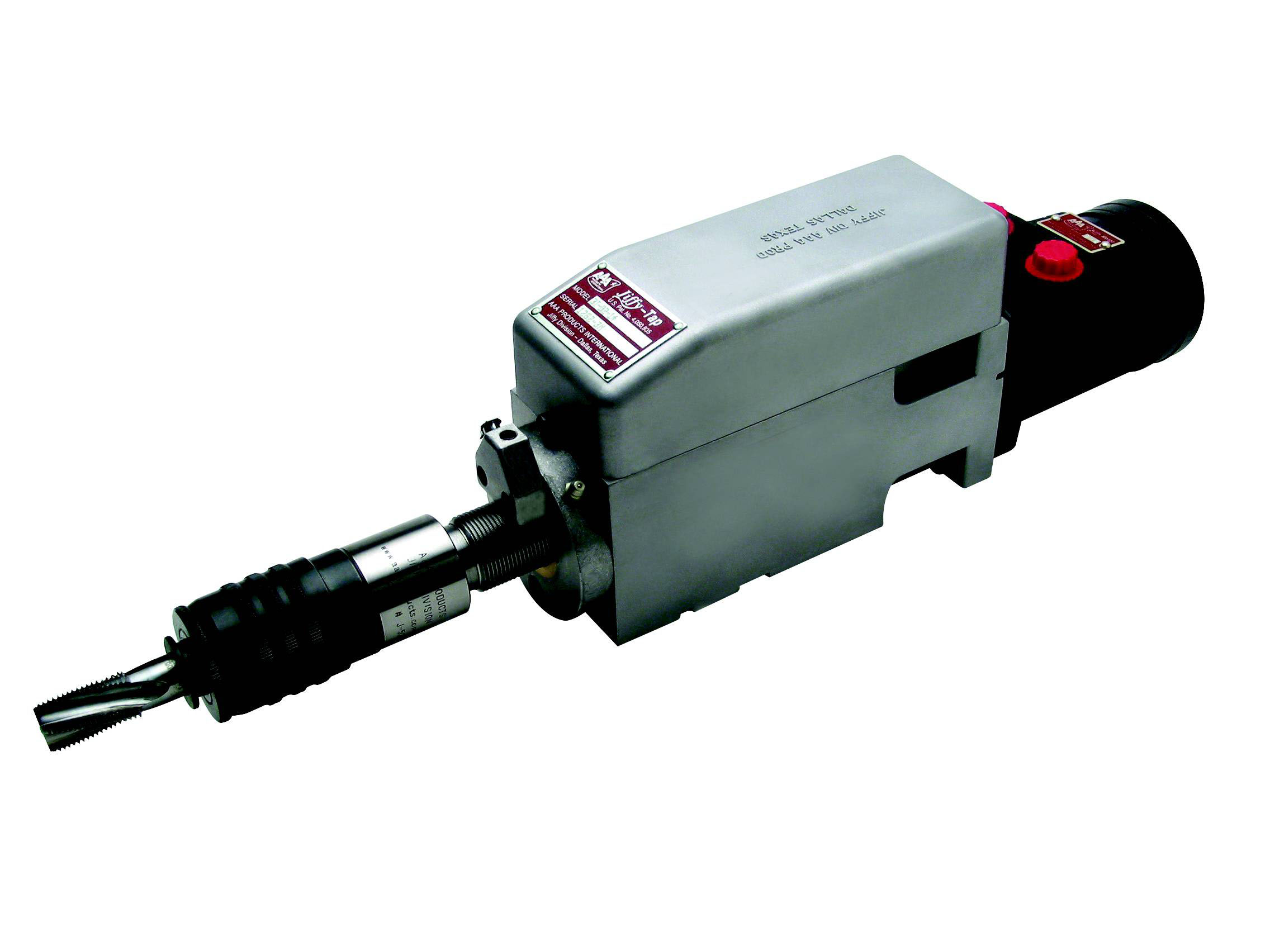
What is a Jiffy-Tap
Jiffy-Tap is the light, compact, and powerful answer to production lead screw tapping or die threading in close quarters. It will easily drive taps up through 1-1/2" N.C. size in medium cast iron with ample allowance for dull taps. Using a hydraulic motor to rotate the spindle, the standard unit will produce more than 10 HP, yet is so compact that two units will mount side-by-side on 3-5/16" spacing. On special orders this can be reduced to 3-3/16". The maximum length from end of motor to end of tap chuck is less than 20". No other tapping unit can deliver the long life and high torque of the Jiffy-Tap in such a small frame.
Jiffy-Tap Stroke
The stroke of the standard Jiffy-Tap unit is 2-1/8", the extended stroke option increases the stroke to 3-3/8". The Jiffy-Tap operates by an SAE 6-spline sliding torque transfer joint. This allows the transfer of horsepower from the stationary drive unit to the linearly advancing spindle. At rest, the drive shaft is retracted into this splined fitting and has maximum spline engagement. As the spindle is advanced forward, this engagement is reduced. As the amount of spline engagement is reduced, the amount of torque that can be transferred to the spline is also reduced. Excessive spline wear should not occur with the following recommended stroke limitation. For torques greater than 350 in.-lbs. use the following limitation on stroke: Stroke (in.) = 2.125 - Torque (in.-lbs.) / 850. For extended stroke units add 1.25 to available stroke.
How a Jiffy-Tap Works
Spindle Rotation: The spindle is rotated by your choice of drive style option. We recommend using compact hydraulic motors for greater power. Although in many applications alternative methods to rotate the spindle may be beneficial. Reversals of 120 times per minute (or more) are no problem for the Jiffy-Tap.
Spindle Advance: The Jiffy-Tap is a lead screw tapping unit. As the spindle rotates, the spindle is either advanced or retracted depending upon the direction of spindle rotation and lead screw pitch. The lead screw pitch is the same as the pitch of the hole to be tapped.
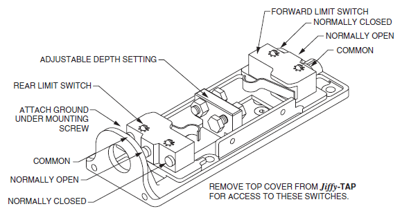
Position Switches: Built-in electric limit switches (part number J-282) and
adjustment screws are used to provide spindle location feedback
to your control circuit. The use of these switches is
entirely dependent upon your control circuit and how you
choose to operate the Jiffy-Tap unit.
Both the rear limit switch and the depth switch are
securely mounted to the switch plate and sensor trigger
adjustments are easily made by adjusting the appropriate
trigger screw.
General Information
The Jiffy-Tap is designed specifically to tap both small holes and large holes in a variety of materials. The size of hole and the material determines the power and RPM required to perform the task. In most cases a single motor is not capable of doing a wide range of holes or materials. In these cases, the motor can be changed to achieve the best power and RPM needed. Although in some cases, you can sacrifice tapping cycle times to reduce the number of different motor sizes needed.
Mounting the Jiffy-Tap
Jiffy-Tap units may be mounted in any position. However, if they are to be mounted with the switch cover down, two 1/8" diameter holes should be drilled in the cover, one at each end, to allow drainage of any hydraulic oil which might leak past the shaft seal in the hydraulic motor. If any drainage is noticed, a new shaft seal kit for the motor should be ordered. Like all seals on hydraulic equipment, the motor shaft seal may have to be replaced after extended service. Instructions for replacing the motor shaft seal are included with the seal kit.
To hold the Jiffy-Tap securely, four mounting holes are provided. Mounting bolts, 1/2"-13, should be used, and should be long enough to engage the Jiffy-Tap body to a depth of 5/8". An alignment groove, 5/8" wide and 3/32" deep is provided in the base of the Jiffy-Tap body. With this groove, the Jiffy-Tap can be accurately re-aligned with the work after having been removed for use elsewhere.
If tapping a brittle material that may produce fine granular chip dust, avoid tapping vertically upward, or use an extension on the tap with a rotary seal to prevent chip dust from getting into the Jiffy-Tap spindle bearing. Avoid washing fine cuttings into the lead screw with the coolant by directing the coolant flow away from the lead screw. Also use a strainer on the coolant to prevent fine granular chips from packing into the lead screw nut, causing it to lock.
Tap Stroke and Spindle Adjustment
The spindle spline will disengage from the hydraulic motor at about a 2-1/2" extension. To prevent damage to the spline, it must always be sufficiently engaged. (If longer strokes are needed, see our extended stroke option.)
The spindle should not be allowed to bottom out on the retraction stroke because the thrust may force the lead screw nut out of its housing. (If this should happen, it can be pressed back in.) The switch actuator block and rear actuator screw have been designed, and have been factory set, to stop the spindle about 1/16" from the bottom out position. Normally, the position of the rear limit switch need not be adjusted. In practice, however, either switch can be set to stop the spindle at any position, forward or reverse, although in extreme cases, the standard 1/4"-20 x 3/4" actuating bolt may have to be replaced with a longer one. Be sure that the longer bolt will not damage the opposite switch.
When changing the depth of stroke or the retract position, carefully cycle through the tapping process manually. This is accomplished by using a JOG button in the circuit. You can determine potential problems prior to any damage to the unit or control switches by slowly advancing the lead screw to verify proper setup.
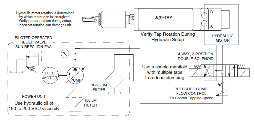
Hydraulic Setup
A hydraulic power unit to operate a Jiffy-Tap is not part of the Jiffy-Tap but may be ordered as auxiliary equipment, or perhaps a standard hydraulic power unit already on hand can be used. Hydraulic hoses should be ordered locally after the distance between the power unit and the tapping unit is established. Several Jiffy-Tap units which are powered with hydraulicmotors can be run from one hydraulic power supply.
Hydraulic to Rotate and Advance Spindle
Flow for spindle motor will be determined by desired RPM on each Jiffy-Tap. Several power arrangements may be used: two (or more) pumps driven from the same or from opposite ends of a double shaft electric motor; a two-section (or more) hydraulic pump; two (or more) separate hydraulic power units. A pressure compensated pump may be used for the main motor drive. Spindle rotation is determined by which port is connected to the hydraulic pump. During setup, verify tool rotation. With lead screw spindles, the spindle is advanced or retracted depending upon the rotation of the spindle.
Choose a hydraulic motor from motor tables that will deliver the required torque and RPM. If you will be using an existing power unit, you will be limited by the pressure and flow available from your existing power unit. On new applications try to keep operating pressures around 600 - 800 PSI and GPM at 25% to 75% of maximum GPM the motor can operate at.
On jobs where several Jiffy-Tap units are to be used, one large power unit can serve all the units by having one or more large pumps and with pressure compensated flow control valves installed in each Jiffy-Tap motor circuit.
Recommended Jiffy-Tap Hydraulic Circuit
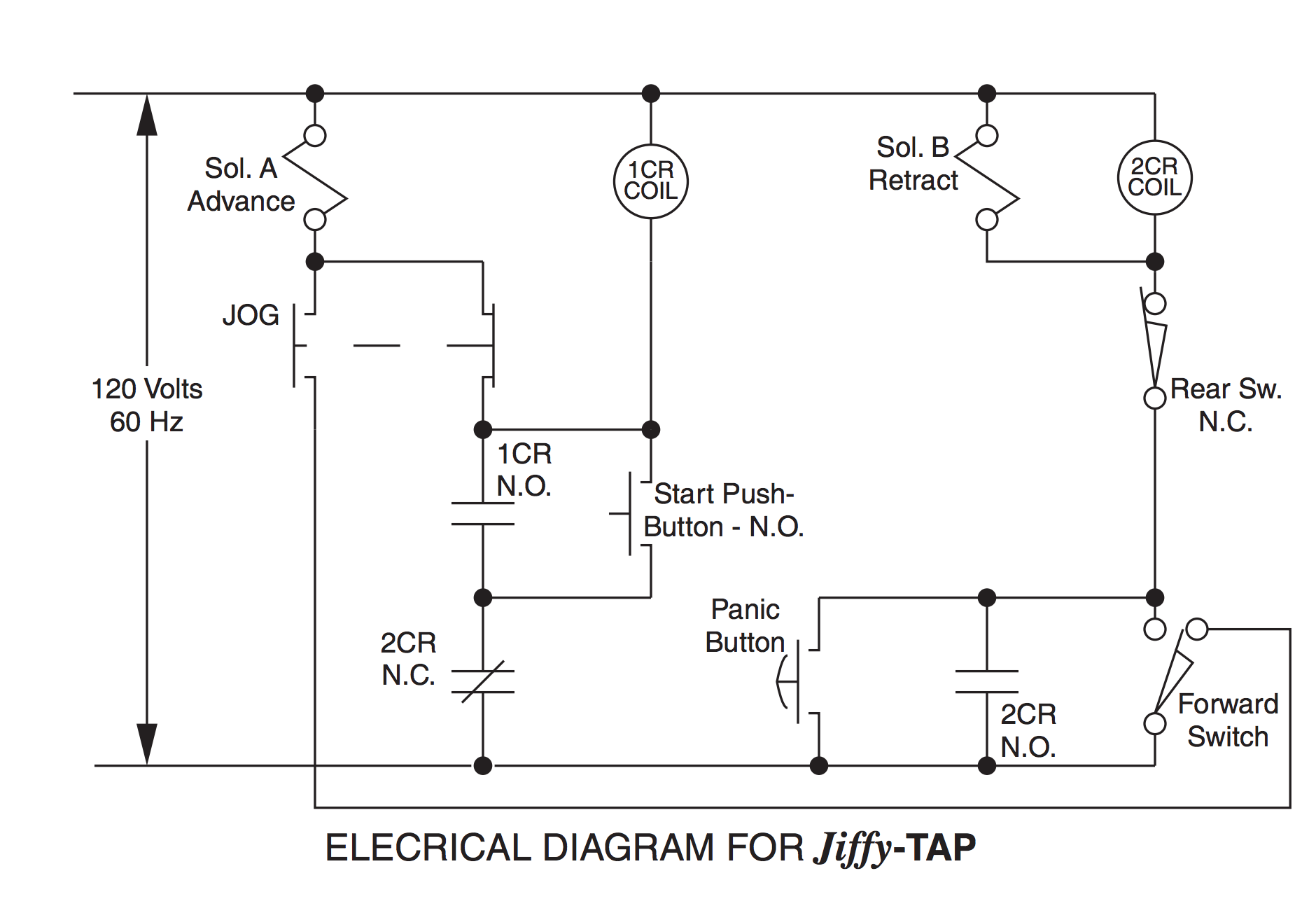
Electric Control of the Jiffy-Tap
Two built-in electric limit switches (part number J-282) mounted inside the top cover of the Jiffy-Tap are of high quality with a life expectancy of 20,000,000 cycles. Each switch has a common, a normally open (N.O.), and a normally closed (N.C.) set of contacts, permitting them to be used in almost any electrical control circuit devised for the Jiffy-Tap. On Standard basic Jiffy-Tap units these switches are not wired, and the external wiring is brought through the conduit hole in the rear of the switch cover. Electrical Option EP is a 12-foot cable wired to all terminals on the switches and to frame ground, and brought in through an 8-pin plug and socket in the switch cover. This permits the Jiffy-Tap to be unplugged quickly from its wiring. (Limit switches are rated up to 4 amps at 125 volts A-C or 1/2 amp at 125 volts D-C. Use relays, if necessary, to control higher current or voltage.)
The position of both limit switches may be adjusted to control tapping depth and retracted position of the spindle. If a switch should fail, or if the control valve spool should fail to center when both solenoids are de-energized, the Jiffy-Tap spindle might over travel. However, precautions have been taken in the Jiffy-Tap design to minimize damage (if any) if such a failure should ever occur.
If the spindle should over travel on its forward stroke, chances are that the tap would simply stall in the work piece, especially on tapered pipe threads, provided the relief or compensator valve on the hydraulic power supply has been properly set. If the relief or compensator valve has been set too high, the tap (especially a small tap) may break, or the advancing spindle may cause the two 6-32 mounting screws on the forward limit switch to break off. After the cause of the malfunction has been corrected, these mounting screws can be replaced. If the spindle should continue to advance, the internal spline will disengage before serious damage is done to the lead screw nut. This disengagement occurs at about 2-1/2" extension of the spindle.
If the spindle should over travel on its return stroke, the lead screw nut may be pushed out of its press fit in the housing. After the malfunction has been corrected, the nut can be pressed back into its housing and secured with two screws in a new place.
If the spindle should lock up in its retracted position and will not start forward, the rear limit switch adjustment may be incorrect, letting the spindle bottom against the hydraulic motor shaft. To release the jam, use a strap wrench to screw the spindle out one turn. Never use a wrench on the threaded portion of the lead screw. Set the limit switch actuating screw 1/16" toward the rear switch, then lock it. If spindle cannot be turned with a strap wrench, loosen the three screws holding the nut.
Parts Drawings and Information
For parts and dimensional drawings please use the product selector to get information about your specific model.
Routine Maintenance Items
Tap Lubrication and Coolant: Jiffy-Tap units are properly lubricated at assembly, and should be checked periodically, especially if running under unusually severe conditions or located where coolant splash tends to wash lubricant off the spindle threads. Re-lubrication points are the spline end of the spindle, the switch slide bar, the switch fork, the switch fork disc, and lead screw threads. Access to these points is by removal of the switch cover, and the switch mounting plate. Coat the above parts with a high film strength grease. These lubrication points should be checked occasionally as a precautionary measure.
The felt wiper which keeps the spindle threads lubricated should occasionally be oiled with 10 to 20 weight engine or machine oil. Once a year it should be removed, cleaned, and re-oiled and replaced if worn. This spring loaded felt wiper clears chips off the spindle as it retracts, as well as lubricating the spindle threads.
Tapping or threading should be done with a good grade of lubricant/coolant. Your local supplier can recommend the best type for the material being worked.
It is best to have the coolant coming out of the tap flutes, toward the Jiffy-Tap if possible. This helps to wash out chips which otherwise would load the tap. This is especially important when cutting taper pipe threads because, as the tap is being retracted, chips fall into the threads and are crushed. On many jobs of pipe thread tapping, the coolant can be pumped through the bottom of the hole, and will flow outward toward the Jiffy-Tap. On jobs where this is not possible, the parts should be flooded with coolant to carry away chips and heat and to lubricate the tap.
Once each month put a very small shot of high film strength grease in the grease fitting located on the lead screw nut housing. Care must be taken when greasing the lead screw through the grease fitting. Excess grease will squirt out of the lead screw nut and become a potential chip collector. These chips would eventually work their way between the lead screw spindle and the lead screw nut, causing the lead screw to seize and lock-up. Remove any excess grease from the front of the lead screw nut.
Hydraulic Drive Motor: This motor is lubricated by the hydraulic oil and needs no other lubrication. Should the shaft seal ever need replacing, seal kits are available from the factory, complete with instructions.
Inspecting Lead Screws: The lead screws should be inspected for impacted chips, excessive wear and unusual wear patterns. The lead screws should be evaluated on a maintenance schedule that is in conformance with the environment that the tap is operating in.
Limit Switches: Routinely inspect limit switches for loose contacts, damaged trigger levers, broken or worn mechanisms, and general structural rigidity.
Removing the Lead Screw Spindle
To change to a different thread lead, the Jiffy-Tap spindle must be changed. Order additional spindles in any standard thread from 6 to 40 threads per inch, N.F., N.C., or metric.
No more than 5 - 10 minutes should be required to replace the spindle. Please follow these steps in sequence:
- Be sure to cut off all electrical power to the Jiffy-Tap unit before working on it.
- Loosen 3 screws and take off switch cover.
- Remove 4 socket head screws, which hold the switch plate, but do not remove the plate.
- Remove 3 socket head screws, holding the lead screw nut housing to front of Jiffy-Tap.
- Lift the limit switch plate, and the limit switch slide bar, just far enough to disengage the slide bar from the disc on the spindle.
- Pull out the complete spindle assembly from the front of the Jiffy-Tap.
Installing a New Lead Screw Spindle
- Screw the new lead screw nut and housing assembly on the spindle to about the same position as the old nut and housing on the spindle just removed.
- Insert the complete spindle assembly into the Jiffy-Tap body, lifting the slide bar slightly so the fork on the slide bar can clear the disc on the spindle. Slightly rotate the spindle to engage the spline.
- Lower the fork on the slide bar to engage the disc on the spindle. To check for engagement, move the spindle in and out. The slide bar should move with it.
- Position the limit switch plate. Insert and tighten 4 screws.
- Install and tighten the 3 screws which hold the lead screw nut housing to the Jiffy-Tap body. Caution: As you tighten these screws, be careful that the rear limit switch actuating bolt does not jam into and damage the rear switch, and that the spindle does not bottom out against the end of the hydraulic motor shaft, in case the lead screw nut was not positioned correctly when it was installed.
- Turn on electric power to the Jiffy-Tap unit.
- Cycle the unit under power, jogging it to see that the limit switch bar is operating and that spindle reversal takes place at the desired position.
- Set the position of the forward limit switch actuating bolt for the desired tapping depth and lock with the jam nut. The rear switch actuating bolt has been factory set to leave about 1/16" gap between the lead screw spindle and the end of the hydraulic motor shaft when spindle is retracted. It can be adjusted to leave more gap, if desired, but should not be set to allow the spindle to bump the motor shaft.
- Replace the switch cover.
Interchanging Hydraulic Motors
In setting up for a different job, the hydraulic motor can be interchanged with a different model which may have a more favorable ratio of torque and speed for the new job.
Remove four socket head bolts. Pull out the motor with spline sleeve still attached. The spline sleeve set screws are swedged in place and removal might be difficult. It is recommended when using interchangeable motors, that you keep the spline sleeve attached and not to swap sleeves between motors. If removal of sleeve is necessary, the swedge must be removed by deburring or a small end mill to remove swedge. Remove set screws, and pull spline sleeve off of motor shaft. Transfer motor ring if used, to the new motor shaft. Place the spline sleeve on new motor shaft, insert and tighten set screws. Plug the new motor assembly into the Jiffy-Tap body, engaging the spline sleeve with the spline on the spindle. Reinstall and tighten the four socket head cap bolts.
Recommended Spare Parts
At least one spare limit switch (part number J-282) should be kept on hand for replacement in an emergency. When replacing a limit switch, transfer one wire at a time from the old to the new switch, to avoid the possibility of getting the new switch wired incorrectly.
In high production applications an extra lead screw should also be kept on hand.
Locating Unit Serial Number
The unit serial number is located on the right side of the unit when looking at the spindle end. Be aware that the covers between units are interchangeable. Therefore, the part number on the cover may not be the correct part number of the unit. Consult the factory for determining the exact part number of your unit or locating the serial number. Serial number may be required when ordering replacement parts.
Factory Repair
The factory can repair units or lead screws at a fraction of the replacement cost for units that need extensive repair or lead screw replacement. Each unit received will be evaluated and the best repair/replace scenario will be provided to the customer.